


16
MICRONAIR AU8000 SPRAYER
7.3. Maintenance of Sprayhead
The AU8000 sprayhead is built from chemical resistant materials and its simple design and
robust construction will ensure many years of trouble-free performance provided that it is
not mistreated and is properly cleaned after use.
The AU8000 atomiser is dynamically balanced to ensure that it will run smoothly without
vibration. Some chemicals, particularly certain ULV formulations, can dry or crystalise on
the gauze, blocking the mesh and causing the atomiser to vibrate. This can easily be
avoided by spraying 1 – 2 litres of liquid from the atomiser at the end of each spray job.
The liquid must be a solvent for the chemical which has been used. Water will normally
only dissolve water-based formulations. kerosene or diesel fuel is suitable for most ULV
products.
The bearings of the AU8000 are sealed and are lubricated for life. The bearings should be
replaced if they become worn.
If it is necessary to replace the bearings or any other part, the procedure to dismantle the
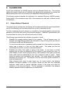
sprayhead is as follows (see Fig. 5):
NOTE: DO NOT remove bearings unless worn.
1. Remove the inlet hose (11) from the restrictor tube on the chemical valve.
2. Loosen the handle clamping screws and slide the handle and sprayhead off the air
inlet tube (19).
3. Remove the bolt of the V clamp (15) and remove the ring from the outer casing.
4. Pull the two halves of the outer casing apart and remove the atomiser (1) and its
support ring (3). Push the feed hose through the grommet in the housing whilst
withdrawing the atomiser
5. Remove the pipe clip (12), inlet hose (11) and cone (5).
6. Remove the pipe union (7) and atomiser securing nut (112). Slide the atomiser from
the support ring.
To dismantle the atomiser, proceed as follows (see Fig. 6):
7. Remove the four screws (118) from the blade clamp ring (103), lift off the ring and
remove the blades.
8. Remove the three screws (122) securing the cap and deflector assembly (105). Pull
the cap from the end of the gauze and push the spindle (102) through the atomiser.
9. If it is necessary to remove the gauze, insert a screwdriver through the holes in the
rear of the gauze and take out the three screws (120) securing the gauze to the hub.
10. If it is necessary to remove the bearings, use a pair of circlip pliers to remove the
circlip (117) the wavy washer (121) and the sealing ring (110) from the front of the
hub. Next, push an aluminium or brass drift against the inner part of the rear bearing
and tap both bearings out through the front of the hub. Ensure that the hub (101) and
spacers (106 and 107) are not damaged or lost.