


2
MICRONAIR AU8000 SPRAYER
3. ASSEMBLY
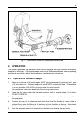
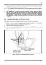
These instructions apply both to AU8000 sprayheads supplied as part of a complete
sprayer and to sprayheads supplied as conversion kits. The steps with numbers in square
brackets [ ] refer to conversion kits ONLY and should be disregarded when assembling a
sprayer supplied complete. There may be some minor differences when installing
conversion kits on some models of sprayer. Parts are identified by their reference number
in Fig. 5.
[1.] Ensure that the mistblower is empty, clean and in good running order.
[2.] Disconnect the chemical feed hose from any existing on/off valve or flow regulator.
Leave the feed hose connected to the chemical tank.
[3.] Remove the original spray nozzle and outlet, leaving only the flexible air duct
attached to the blower.
4. Insert one end of the rigid air tube (19) into the inlet of the sprayhead so that 40 mm
of tube is inside the casing.
5. Slacken both clamping screws of the handle and valve assembly (13). Slide the
handle over the air tube with the handle angled towards the sprayhead. Position the
handle with one clamp over the slotted inlet of the sprayhead casing and the other on
the air tube. Tighten both clamping screws to grip both the sprayhead and air tube.
6. Temporarily insert the free end of the air tube into the flexible air duct from the
mistblower.
7. Put on the knapsack mistblower and hold the sprayhead at the correct angle for the
crop or pest to be sprayed. Cut the air tube (19) as required to give a comfortable
position for the sprayhead when held by its handle. The sprayhead should also be
rotated to the most convenient position.
8. Place a pipe clip (20) over the end of the flexible air duct and tighten the clip to grip
the air tube.
9. Push the feed hose from the chemical tank on to the inlet fitting (17) of the control
valve. Note that this fitting is stepped to accept varying sizes of hose. If necessary,
the hose should be cut to length or replaced if it is too short. Secure the hose with
the pipe clip (12) provided.
10. Select the appropriate flow restrictor tube (8) (see section 6) and fit this to the outlet
of the on/off valve using the cap nut (14). Ensure that the filter (16) is in position.
11. Connect the atomiser feed hose (11) to the outlet of the flow restrictor and secure
with a pipe clip (12).
12. Fill the tank with a non-toxic liquid (e.g. water for conventional application or
kerosene for ULV) and run the sprayer for several minutes (see Operation section 4)
to test for leaks.