


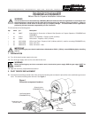

Insert a 5/16”
(7.94mm) drill
bit to measure
opening
(remove before
operation)
Blowers without
external air shutter
OR
External
air
shutter
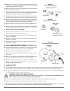
6. INLET PRESSURE CHECK
6.1 Check the gas control inlet pressure at the inlet pressure tap. See Figure 6. An inlet pressure of 6-14” (14.9-34.9mbar) is
recommended for propane operation.
6.2 If the inlet pressure is:
• HIGHER THAN 14” W. C. (34.9mbar) - This pressure may damage the combination gas control valve. Decrease the supplied
gas pressure.
• LOWER THAN 3” W. C. (7.46mbar) - It may be necessary to increase the supplied gas pressure.
If it is necessary to adjust the gas line pressure, have the customer contact the gas utility supplier.
7. PILOT PRESSURE ADJUSTMENT
7.1 Ensure that the air supply is properly adjusted for propane operation.
• Units with a burner blower air shutter (see Figure 5) should have the shutter opening (at its outside edge) set to 5/16”
(7.94mm). A drill bit can be used to check the adjustment of this opening.
• Units without the air shutter (see Figure 5) should have the burner air supply adjustment screw turned 11-17 full revolutions
clockwise from the fully closed (counterclockwise) position. The screw is located on the front wall of the burner plenum, and
is surrounded by a “MORE AIR” label.
8.2 If necessary, adjust the pressure regulator as follows:
• Remove the pressure regulator cap screw.
• Using a screwdriver, turn the inner adjustment screw clockwise to increase, or counterclockwise to decrease, the main
burner gas pressure.
• Replace the cap screw and tighten it firmly.
8.3 Record the final measured regulated gas pressure on the silver conversion information label (included in the kit).
7.2 Before proceeding:
• For a PS360EWB oven, the set point should be reduced
below the room temperature.
• For a PS360WB70 oven, set the oven to low flame.
7.3 Measure the pilot pressure at the pilot pressure tap, as shown
in Figure 6. The gas pressure should be 5-6” W. C. (12.5-
14.9mbar) for proper operation.
7.4 If necessary, adjust the pilot pressure as follows:
• Remove the pilot adjustment cap screw.
• Using a screwdriver, turn the inner adjustment screw
counterclockwise to increase, or clockwise to decrease,
the pilot gas pressure.
• Replace the cap screw and tighten it firmly.
7.5 Measure the current across the pilot flame sensor. The
current must measure at least 2.0
µA. If the current reading
is too low, recheck the pilot pressure as per Step 7.3. If the
pressure reading is correct, consult the factory; otherwise,
repeat Steps 7.4 and 7.5.
8. MAIN MANIFOLD PRESSURE ADJUSTMENT
8.1 With the oven set to high flame, measure the regulated gas
pressure to the burner. The outlet pressure should be
checked at the main orifice pressure tap. See Figure 6.
The gas pressure should be 3” W. C. (7.46mbar) for proper
operation.
Figure 5
Burner blower configurations
p/n 36857 P. Jan 98 Rev. B Page 3 of 4
Figure 6
Gas pressure measurement/adjustment locations
Inlet pressure
tap
Pressure
regulator cap
screw
Pilot
adjustment
cap screw
Pilot tube
connects
here
Pilot pressure
tap
Main orifice
pressure tap