


OM-188 304 Page 15
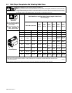
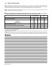
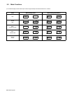
4-3. Remote 14 Receptacle Information
Socket* Socket Information
AJ
24 VOLTS AC
A 24 volts ac. Protected by circuit breaker CB2.
AJ
B
K
I
C
L
NH
24 VOLTS AC
B Contact closure to A completes 24 volts ac
contactor control circuit.
C
L
NH
D
M
G
F
115 VOLTS AC
I 115 volts ac. Protected by circuit breaker CB1.
E
F
115 VOLTS AC
J Contact closure to I completes 115 volts ac
contactor control circuit.
C Output to remote control; +10 volts dc.
REMOTE
OU
TP
U
T
D Remote control circuit common.
OUTPUT
CONTROL
E 0 to +10 volts dc input command signal from
remote control.
A
/
V
F Current feedback; +1 volt dc per 100 amperes.
A/V
AMPERAGE
VOLTAGE
H Voltage feedback; +1 volt dc per 10 output recep-
tacle volts.
GND
G Circuit common for 24 and 115 volts ac circuits.
GND
K Chassis common.
*The remaining sockets are not used.
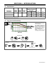
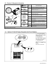
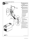
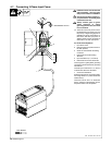
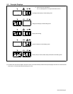
4-4. Optional 115 Volt AC Duplex Receptacle And Circuit Breakers
ST-801 245-A
1 115 V 10 A AC Receptacle
Power is shared between duplex
receptacle and Remote 14 recep-
tacle (see Section 4-3).
2 Circuit Breaker CB1
CB1 protects duplex receptacle
and 115 volt ac portion of Remote
14 receptacle from overload.
3 Circuit Breaker CB2
CB2 protects 24 volt ac portion of
Remote 14 receptacle from
overload.
Press button to reset breaker.
2 3
1