


3
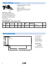
VOLT/AMP CURVES
MINIMUM AND MAXIMUM - STICK MODE
AMPERES
VOLTS
0
10
20
30
40
50
60
70
80
0 100 200 300 400 500 600
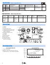
DUTY CYCLE CHART
WELD AMPERES
% DUTY CYCLE
0102030405060708090100
100
150
200
250
300
350
400
DC Weld
AC Weld
VOLT/AMP CURVES
MINIMUM AND MAXIMUM - MIG MODE
AMPERES
0 100 200 300 400 500 600
0
10
20
30
40
50
60
70
80
VOLTS
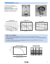
GENERATOR POWER CURVE
AC VOLTS
AC AMPERES IN 240V MODE
AC AMPERES IN 120V MODE
300
250
200
150
100
50
0
150
125
100
75
50
25
0
0102030405060708090
0 20 40 60 80 100 120 140 160 180
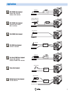
SIMULTANEOUS WELDING
AND GENERATOR POWER
Weld
Current
(Amps) Watts
120V 1P
Receptacle
Amps
240V 1P
Receptacle
Amps
0
100
150
200
300
350
100
90
80
62
25
10
50
45
40
31
12
5
12,000
11,000
9,500
7,500
3,000
1,000
12 kW
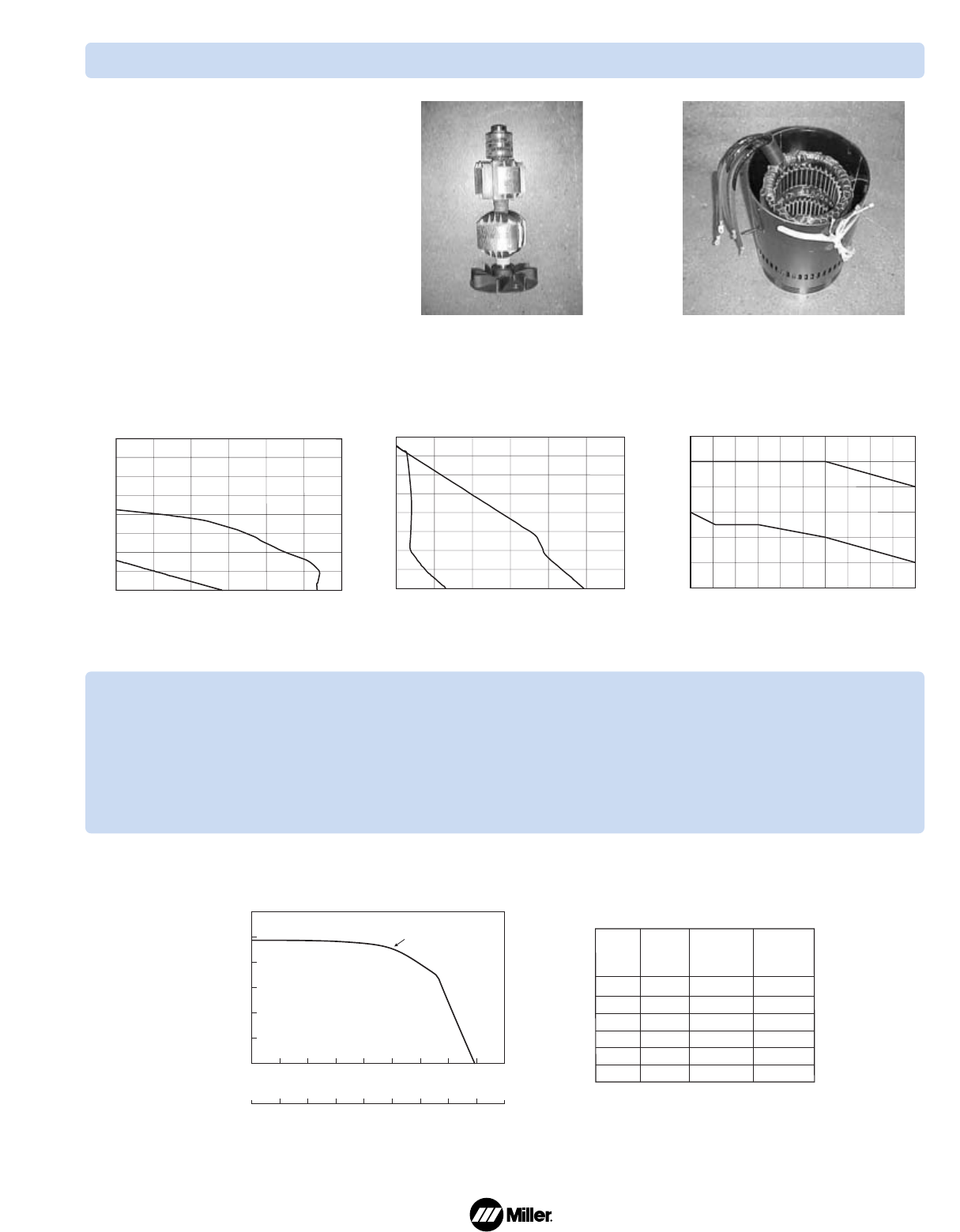
Performance Data (continued)
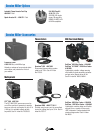
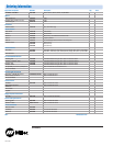
All Trailblazers have 2 generators—
a 4-pole, 3-phase weld generator and a
strong power generator.
TRAILBLAZER ADVANTAGE: No interaction
between grinders, power tools, etc. and
the welding arc. Generator power is also
independent of weld control settings.
POWER IS IN THE NUMBERS
• Tested and rated at higher temperatures, 104˚ F (40˚ C), to ensure consistent operation in all climates.
• Patented generator control technology matches the generator’s output to engine horsepower providing maximum efficiency
and more weld output.
• The generator is voltage regulated to provide strong power while keeping the voltage 120/240 volts. This increases
tool/motor performance and tool/motor life.
StatorRotor