


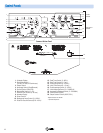
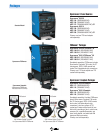
4
Sequencer**
Module
Pulser*
Module
1
8
7
9
10
11
12
13
14
15
16
17
18
2
3
4
5
6
19
20
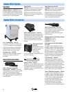
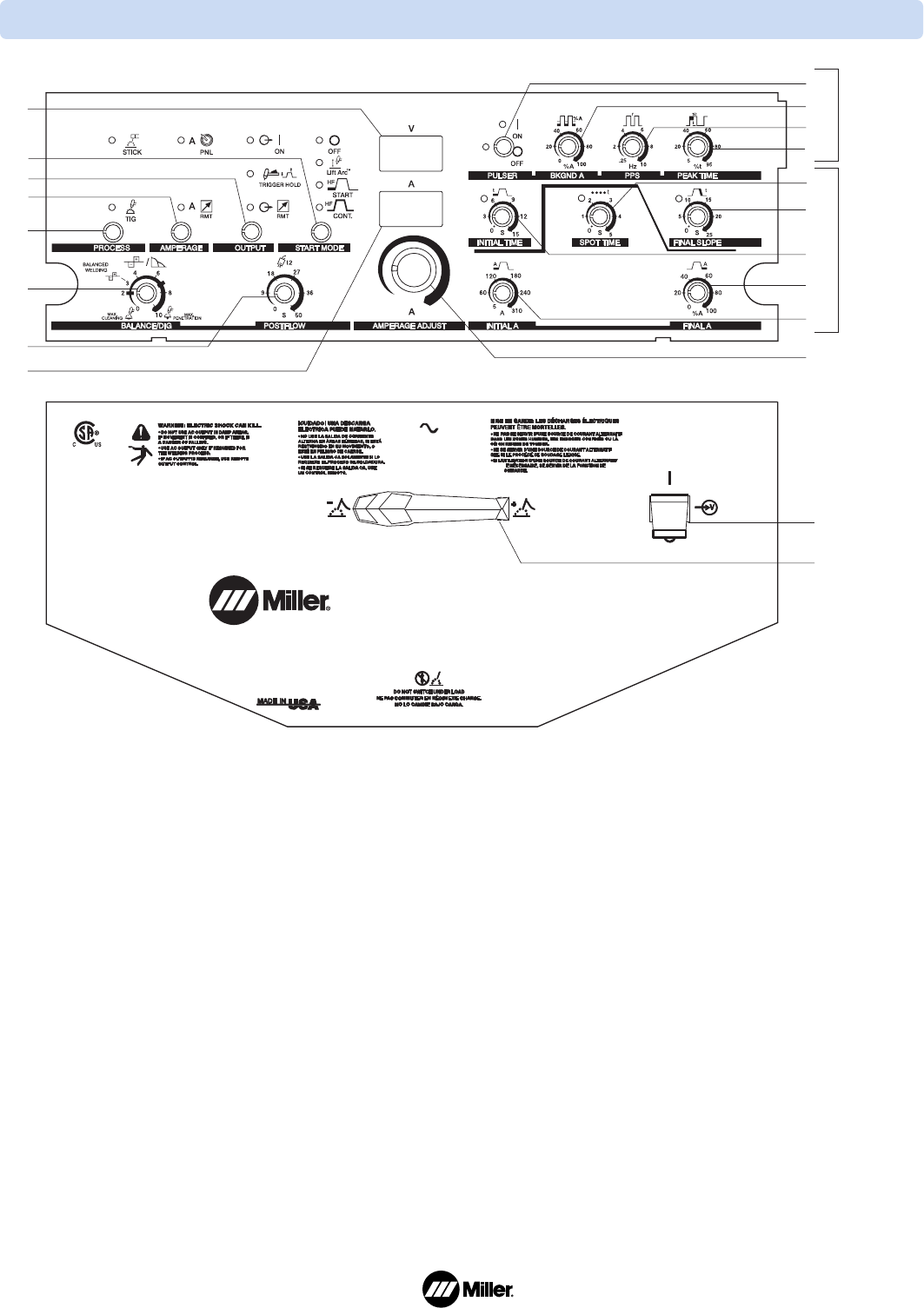
Common Bottom Panel
Control Panels
1. Voltmeter Display
2. Start Mode Control
(Lift-Arc, HF Start, HF Continuous)
3. Output Control
4. Amperage Control (Panel/Remote)
5. Process Control (Stick/TIG)
6. Balance/Dig Control (0–10)
7. Postflow Time Control (0–50 sec)
8. Ammeter Display
9. Pulser Control*
10. Background Amps Control (0–100%)*
11. Pulse-Per-Second Control (0.25–10 Hz)*
12. Peak Time Control (5–95%)*
13. Spot Time Control (0–5 sec)*
14. Final Slope Control (0–25 sec)*
15. Initial Time Control (0–15 sec)*
16. Final Amperage Control (0–100%)*
17. Initial Amperage Control (3–310/400 A)*
18. Amperage Adjustment Control (3–310/400 A)
19. Power Switch (On/Off)
20. Output Selector Switch (AC/DC-/DC+)
*Optional Pulser for 250 DX
**Optional Sequencer