


OM-230 298 Page 19
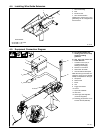
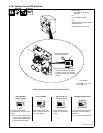
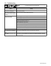
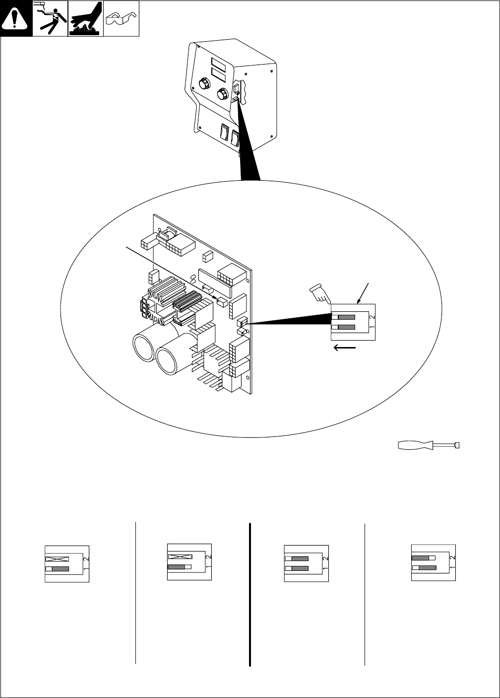
4-16. Setting Internal DIP Switches
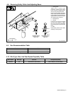
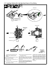
Position Settings And Results For DIP Switch S1 On PC1
Run-In feature is not avail-
able. X - Means switch may
be in either position.
Run-In feature is available.
X - Means switch may be in either
position.
. If 14 pin power cable from pow-
er source does not provide volt-
age and current feedback, Run-
In will automatically disable.
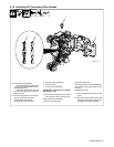
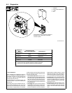
Remove wrapper.
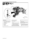
1 DIP Switch S1 On Motor
Board PC1
S1-1
Run-In enable or disable.
S1-2
Automatic Run-In versus Manual
Adjustment Run-in
Install wrapper when finished.
1
803 063 / Ref. 802 944
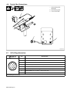
. In the DIP switch S1 illustrations,
the elevated slider on each switch
is shown in white. For example,
the switches above are in the Off
position.
Tools Needed:
1/4 in
Factory Set Default Set-
tings For DIP Switch S1
S1-1
S1-1
Run-In DisabledRun-In Enabled
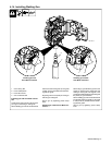
P1
(Factory Default)
Run-In speed is approxi-
mately 1/2 weld wire feed
speed.
Run-In speed is set using poten-
tiometer P1 located on Motor
Board PC1.
. P1 is a 25 turn potentiometer.
S1-1 And S1-2
S1-1 And S1-2
Automatic Run-In
(Factory Default)
Manually Adjusted Run-In