


OM-211 076 Page 21
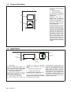
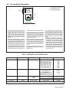
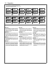
5-9. Process Set Up Push Button
• Press the Process Set Up push button the
first time will illuminate the button LED and
Process LED above the button. Both
displays will show the current process and,
if desired, these displays will be active to
allow selecting a new process. Default
processes are MIG, PULSE, and ACCU
PULSE.
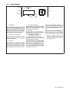
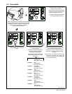
• Pressing the Process Set Up push button a
second time will illuminate the Wire Type
LED and the bottom display will show wire
types available for the selected process. To
make a selection, rotate the Adjust control.
• Pressing the Process Set Up push button a
third time will keep Wire Type LED lit, but the
upper display will be active and show wire
sizes available for the current wire type. To
make a selection, rotate the Adjust control.
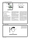
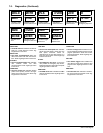
• Pressing the Process Set Up push button a
fourth time will illuminate the Gas Type LED
and both displays will show available gas
selections for the process, and wire type
and wire size selection. To select an item,
rotate the Adjust control.
• Pressing the Process Set Up push button a
fifth time will load the program that matches
the selected parameters (process, wire
type, wire size, gas). The upper display will
show PROG and the lower display will show
LOAD.
If no changes were made to any setup items,
no program will be loaded, and unit will return
to standby mode.
If a custom program is loaded using an
optional PDA with File Management software,
the upper display will show CUST and the
lower display will show PROG. The Adjust
control remains active to allow loading a
standard program in place of the custom
program.
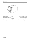
• Pressing and holding the Process Set Up
push button in on power up allows viewing
the software revisions of each circuit board
in the system. The top display shows the
board (PCM, UIM, WFCM, and AIM (auto-
mated units only) and the lower display
shows the last 3 digits of the circuit board
part number plus a letter designator. Press
the flashing Feeder Set Up push button to
exit the screen displays and continue the
power up process.
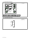
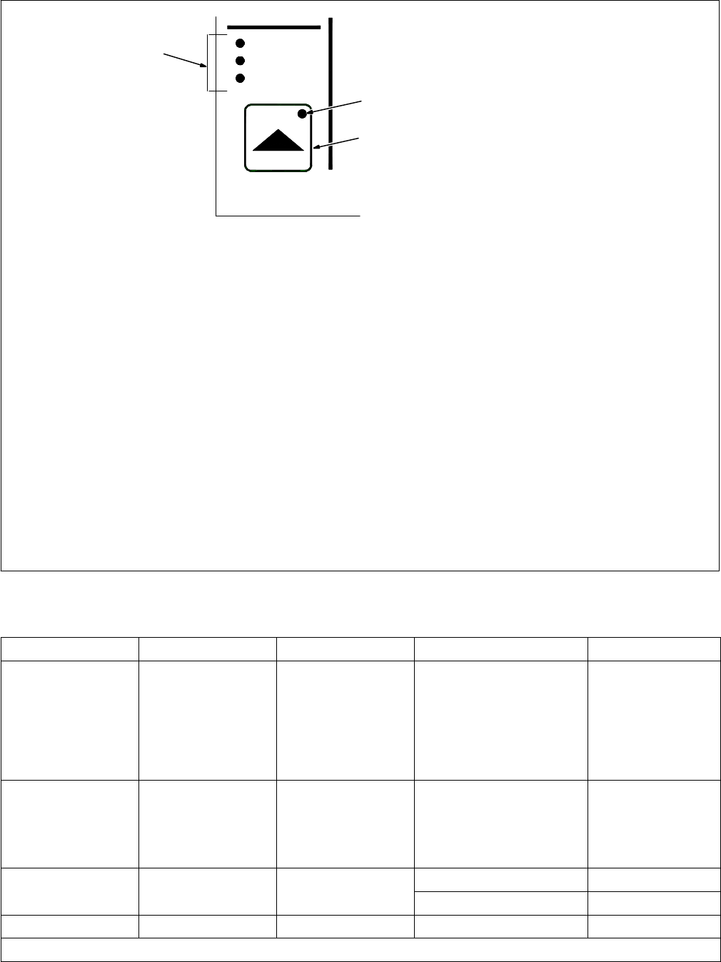
1
3
2
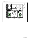
1 Process Set Up Push Button
2 Process Set Up LED
3 Program Selection LEDs
Process
Wire Type
Gas Type
Process Set Up
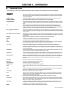
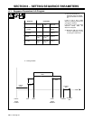
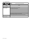
Table 5-1. Welding Wire And Gas Abbreviations*
Wire Description Wire Abbreviation Alloy Type Gas Type Gas Abbreviation
Steel STL E70, E100, E120 100% CO
2
,
90% Argon/10% CO
2
,
85% Argon/15% CO
2
,
75% Argon/25% CO
2
,
95% Argon/5% CO
2
,
95% Argon /5% O
2
,
98% Argon/2% O
2
CO2
C10
C15
C25
C5
OX5
OX2
Stainless Steel SS 308, 309, 312, 316 98% Argon, 2% O
2
(81Ar/18HE/1CO
2
Accu-pulse)
90HE/7-1/2Ar/2-1/2CO
2
MIG/RMD/Accu-pulse)
OX2
Tri Gas
Tri Gas
Cored Tubular Wire MCOR 71, 76, 86R, 409,
439
90% Argon/10% CO
2
C10
439
98% Argon/2% O
2
OX2
Aluminum ALUM 4XXX, 5XXX 100% Argon ARGN
* Not all wire types may be available with your unit.