


OM-4414 Page 5
SECTION 2 − DEFINITIONS
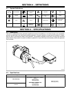
2-1. Symbol Definitions
Circuit Breaker
Read Operator’s
Manual
A
Amperes
V
Volts
Positive Negative
Alternating Current
(AC)
Output
Time
h
Hours Temperature
Protective Earth
(Ground)
Welding Arc
(Electrode)
Work Connection Voltage Input
SECTION 3 − SPECIFICATIONS
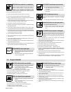
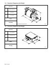
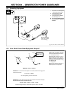
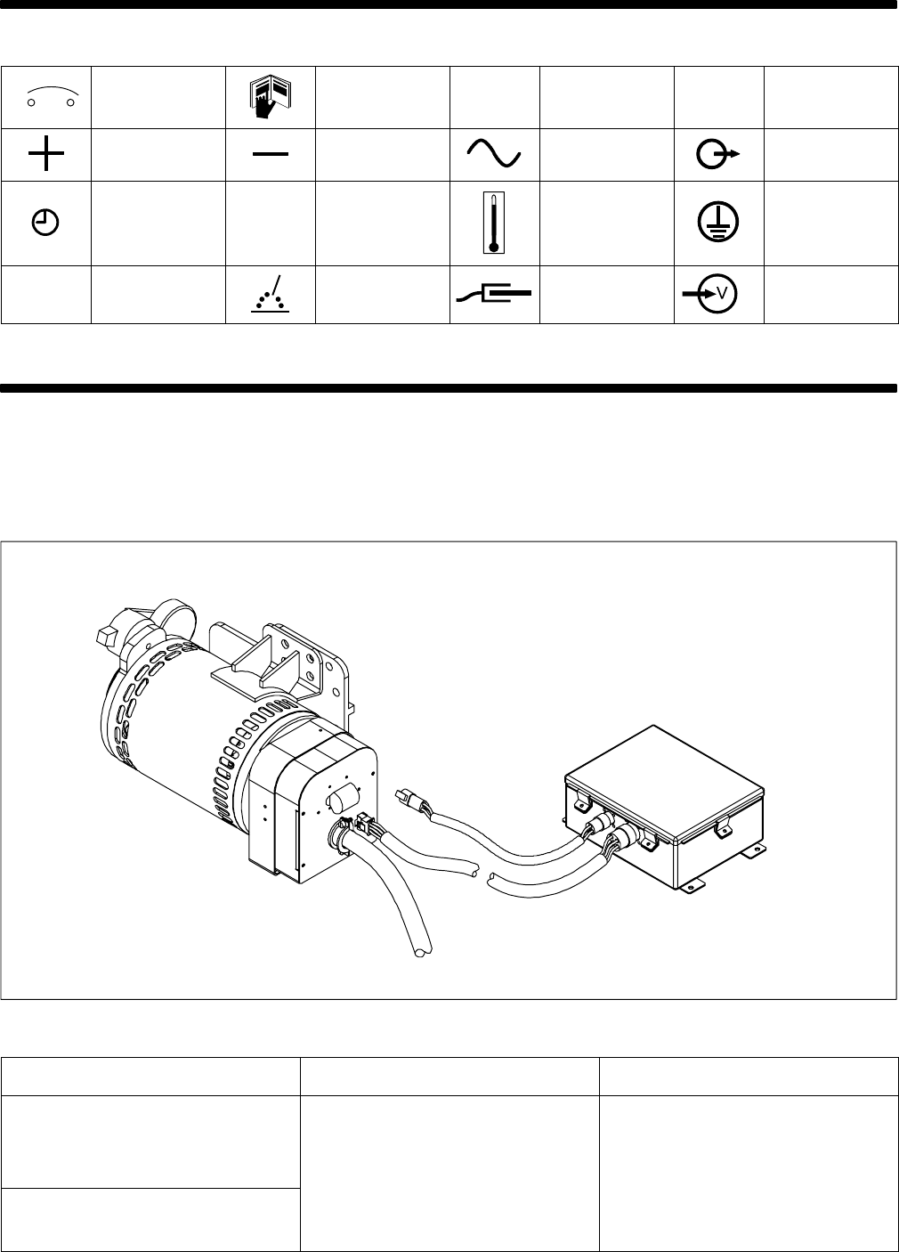
3-1. Description
This belt or hydraulically-driven generator supplies ac power to the platform to run tools through an ac receptacle,
and also operate lights, and cutting and welding equipment. All power regulation components are located in a water-
tight box that is connected by cable to the generator. The generator supplies power when running at the specified
speed with the Power switch on (switch is located on platform). A 3-pole, 30 Amp circuit breaker protects the generator
from overload.
803 233
3-2. Specifications
Drive-Type Output Generator Speed
Belt-Drive/Pulley
Single-Phase, 6 kVA/kW, 25 A, 120/240 V,
50/60 Hz
10 P F t
B
e
l
t-
D
r
i
ve
/P
u
ll
ey
1.0 Power Factor
100% Duty Cycle
Three
-
Phase 7.5 kVA/kW, 18 A,
3000 rpm (50 Hz)
3600 r
p
m
(
60 Hz
)
Hydraulic
Three
-
Phase 7
.
5 kVA/kW
,
18 A
,
240 V, 50/60 Hz,
1.0 Power Factor
100% Duty Cycle
3600 rpm (60 Hz)