OM-4427 Page 73
Description
Part
No.
Dia.
Mkgs.
Item
No.
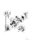
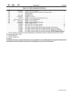
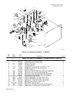
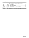
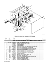
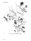
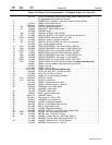
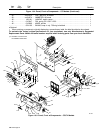
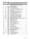
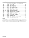
Figure 13-3. Control Box Assembly − CC/CV Models (Continued)
Quantity
20 177 136 CLAMP, capacitor 1.375dia 1. . . . . . . . . . . . . . . . . . . . . . . . . . . . . . . . . . . . . . . . . . . . . . . . . . . . . . . . .
21 D1/C1 189 701 DIODE/CAPACITOR BOARD 1. . . . . . . . . . . . . . . . . . . . . . . . . . . . . . . . . . . . . . . . . . . . . . .
22 TD1 214 928 TIMER, delay on make/break open 30 sec 12vdc 1. . . . . . . . . . . . . . . . . . . . . . . . . . . . . . . .
23 CB11, 12, 13 139 266 CIRCUIT BREAKER, man reset 1P 15A 250VAC frict 3. . . . . . . . . . . . . . . . . . . . .
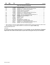
♦Optional
*Recommended Spare Parts.
To maintain the factory original performance of your equipment, use only Manufacturer’s Suggested
Replacement Parts. Model and serial number required when ordering parts from your local distributor.


