


OM-1500-7 Page 27
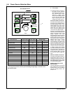
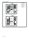
Reset To Factory Settings
A reset menu is displayed if the following four
push buttons are pressed simultaneously:
Program, Sequence, upper display, and Set-
up. The upper display indicates “WIPE” . The
lower display indicates “OFF”. The lower
push button is active indicating that the Adjust
control can be used to change the unit to
“WIPE ON”. When “WIPE ON” is set, if the ori-
ginal four push buttons are simultaneously
pressed a second time, the unit will reset all
settings to factory default except the arc time
and arc cycle counts. If a reset is not desired,
set the display to “WIPE OFF” and simulta-
neously press the Program, Sequence, upper
display, and Setup push buttons to exit the re-
set menu.
Auxiliary Menu
• An auxiliary menu is provided if both the Se-
quence and Setup push buttons are
pressed simultaneously. The Setup push
button and sequence push button LEDS
flash when the auxiliary menu is displayed.
Pushing the Setup push button will step
through the menu. Pushing the sequence
push button will step through the menu in re-
verse.
. The auxiliary menu may be exited at any
time by pressing both the Sequence push
button and the Setup push buttons simul-
taneously.
V-Min And V-Max
• If the Setup push button is pressed, the unit
allows the setting of the manual override
power source min and max voltage preset
range. The minimum voltage is displayed in
the upper display and the lower display indi-
cates “VMIN”. When the Setup push button
is pressed the unit displays the maximum
voltage setting of the welding power
source. The maximum voltage is displayed
in the upper display and the lower display
indicates “VMAX”.
In both cases, the Adjust control is used to
specify the minimum and maximum voltage
settings of the welding power source. The
settings correspond to arc voltage obtained at
minimum command and arc voltage obtained
at maximum command.
This method of setting “VMIN” and “VMAX”
may be used if the power source being used
is not listed in the Power Source Selection
Menu.
. If a default power source has already
been selected with the Power Source
Selection menu, setting “VMIN” and
“VMAX” will override the default power
source settings.
. The power source selection menu must
be set to “OFF” when overriding the de-
fault “VMIN” or “VMAX” settings.
Power Source Selection Menu
• If the Setup push button is pressed, the unit
allows the Power Source Selection menu to
be disabled or enabled.
The upper display shows “PSS”. Lower dis-
play shows “On” or “Off”. The Adjust Control
is used to select either “On” or “Off”.
Arc Time
• If the Setup push button is pressed, the unit
displays arc time in hours.
Arc time is indicated by the Program display
showing “HR”. Arc time is shown in the lower
display.
Cycles
• If the Setup push button is pressed, the unit
displays the number of cycles.
Arc cycles are indicated by the Program dis-
play showing “CL”. The arc cycle count is
shown in the lower display.
Run-In
• If the Setup button is pressed, the unit al-
lows setting the run-in modes. The run-in
modes are program specific. Each program
may be set to its own run-in mode.
The upper display indicates “RUNI”. The
lower display indicates “AUTO”, meaning
the factory set automatic run-in speed is
selected.
Pressing the lower display button allows a
manual setting the run-in wire speed. Speed
may be adjusted from 10% to 100% of weld
wire speed.
Pressing the lower display button allows
disabling of the run-in feature. When the
lower display indicates “OFF” run-in is dis-
abled.
Burnback
• If the Setup push button is pressed, the unit
allows burnback time to be set.
Burnback time and voltage can be specified
when the lower display indicates “BURN” and
the upper display indicates the burnback time
or voltage. The Adjust control is used to set
the desired burnback time or voltage. Burn-
back settings, like run-in settings, are pro-
gram specific. The active program is dis-
played in the Program display and can be ad-
justed (see Section 6-6).
Trigger Hold Setup
• If the Setup push button is pressed, the unit
allows trigger hold delay time to be set.
Trigger hold delay time is indicated by
”HOLD” in the lower display and the hold
delay time in the upper display. The adjust
control can be used to specify a new delay
time for trigger hold. Trigger hold delay time is
the minimum amount of time the trigger must
be held for trigger hold to work when the trig-
ger is released (the trigger hold function must
be on). For example, if a trigger hold delay
time of 2.0 seconds is defined, the operator
must hold the trigger for at least 2 seconds be-
fore releasing it in order for the trigger hold
function to work. Once the trigger hold func-
tion is in effect, the wire feeder will stay On un-
til the trigger is pressed and released again.
• There is an additional function built in called
”maximum trigger hold time” which is the
maximum length of time the trigger can be
held and the trigger hold function still work
when the trigger is released (the trigger
hold function must be on). The maximum
trigger hold time is set at 4.0 seconds after
the trigger hold delay time. For example, if
a trigger hold delay time of 2.0 seconds is
defined, and the operator held the trigger in
for more than 6.0 seconds, the trigger hold
function would not be in effect and the wire
feeder would stop when the trigger is rele-
ased.
• When the Setup push button is pressed
again, the menu repeats to the first menu
selection of run-in wire speed selection.
Trigger Program Select
• If the Setup push button is pressed, the unit
allows Trigger Program Select or Trigger
Dual Schedule to be enabled or disabled.
The upper display shows “TSEL”. Lower dis-
play shows “OFF” or “PROG” or “DUAL”. The
Adjust Control is used to select “OFF” or
“PROG” or “DUAL”.
Trigger Program Select (PROG) allows the
operator to select programs during preflow by
clicking the trigger (pulling and releasing the
trigger in a maximum of 0.2 seconds). The
feeder will switch between any programs that
have a minimum of 0.2 seconds of preflow
time set in the weld sequence. Any combina-
tion of programs may be used. Trigger Pro-
gram Select cannot be used while welding or
with Dual Schedule.
(Example: If programs 1 and 3 have a mini-
mum of 0.2 seconds of preflow time, clicking
the trigger will toggle between programs 1
and 3).
Trigger Dual Schedule Select (DUAL) allows
the operator to switch between paired sched-
ules (programs 1−2, 3−4, 5−6, or 7−8) with the
gun trigger, but only while welding. This fea-
ture cannot be used with Trigger Hold or Dual
Schedule. To end the weld, the trigger must
be released for 0.4 seconds.
(Example: when welding with this feature en-
abled in program 1, if you release, re-trigger,
and hold again within <0.4 seconds, the ac-
tive program will switch to program 2. If the
previous sequence is repeated the active pro-
gram will switch back to program 1. This cycle
can be repeated for the entire weld).
Process Select
Process selection indicated by ”PROS” in the
upper display is set to either ”VOLT” or
”TRIM” in the lower display. Each program
can be selected be be a MIG program indi-
cated by ”VOLT” or a pulsing program indi-
cated by ”TRIM”.
Range Locks
Range locks are indicated by “LOCK” in the
upper display for wire speed or “LOCK” in the
lower display for voltage range. In a MIG pro-
gram, the voltage range lock ranges from 0 to
10 volts. In a pulse program, the trim range
lock ranges from 0 to 100. The wire feed
speed range lock ranges from 0 to 250 ipm.
Locks are program dependent and wire
speed is independent from voltage or trim.
Wire Feed Speed Units
Wire feed speed setting indicated by “WFS”
in the upper display is set to “IPM” inches−
per−minute or ”MPM” meters−per−minute.
This setting is independent of the program se-
lected.
6-12 Auxiliary Menus (Continued)