


OM-1500-7 Page 30
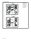
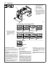
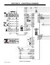
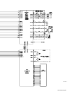
8-2. Diagnostics
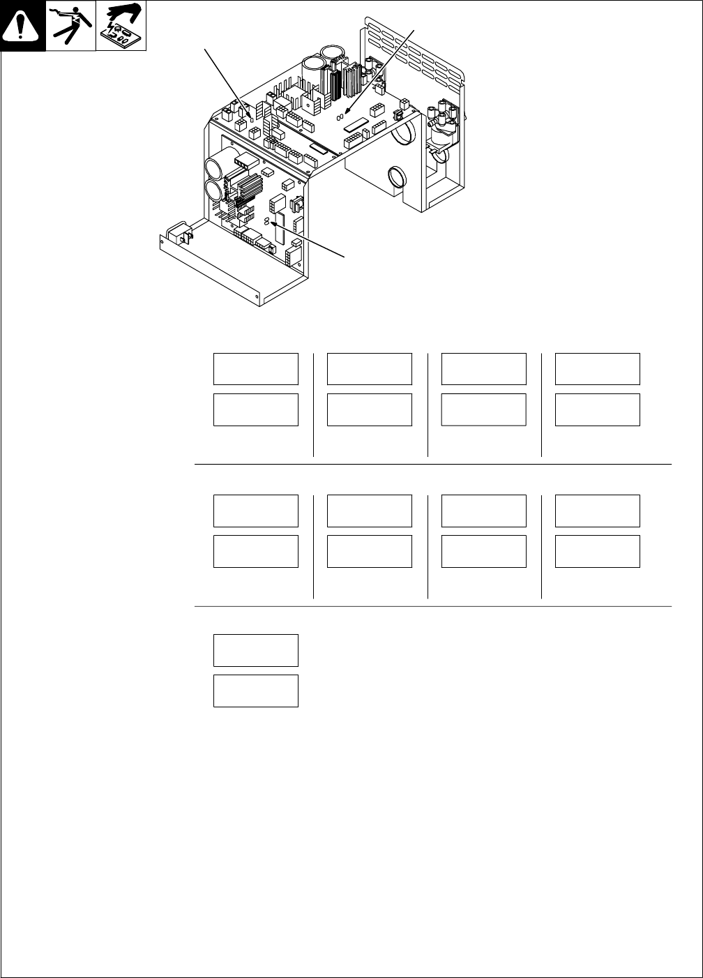
803 063-A
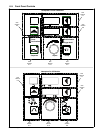
1 LED3 On Right Side Motor
Control Board PC1
2 LED3 On Left Side Motor
Control Board PC101
3 LED4 On Dual Board PC70
. There is a two-position DIP
switch S1 located on motor con-
trol boards PC1 and PC101.
These switches are factory-set
in the off position and must re-
main in that position for the unit to
operate correctly.
LED3-Related Error Indications
Error conditions are indicated by LED3 on
PC1, PC101, and LED4 on PC70. To view
LED3, 4 turn Off unit, remove wrapper, and
turn unit On.
The LED blinks in a 2.5 second cycle. The
number of blinks in this period indicates the
type of error.
The priority of the errors is related to the num-
ber of blinks indicating the error. The more
blinks, the more severe the error (motor error
is top priority). A higher priority error overrides
a lower one (if a motor error and a communica-
tion error existed, the light would blink four
times for the motor error).
Since blink On time and blink Off time are
equal in a four-blink cycle, the four−blink se-
quence appears as a constant blink.
1 blink = Communication Error
2 blinks = Trigger Error
3 blinks = Tach Error
4 blinks = Motor Error
• The communication error occurs 2.5 sec-
onds after a loss of communication between
the motor and the Front Panel board or Dual
board. The user may continue to weld with
this error.
• The trigger error occurs if the user has the
trigger held for more than two minutes with-
out striking an arc (providing current over-
ride is not enabled), or if the user holds the
trigger past the postflow phase in a timed
weld. This error also occurs if the trigger is
held when the feeder is powered up. The er-
ror may be cleared by releasing the trigger.
• The tach error occurs 2 seconds after the
loss of tachometer feedback. The user may
continue to weld with this error. The motor
speed is regulated through the monitoring of
voltage and current.
• The motor error indicates that the motor
has been drawing too much current for too
long.
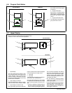
ERR
COM1
ERR
TRG1
ERR
TCH1
ERR
MTR1
. Note: The error messages
are shown on the upper
and lower displays to indi-
cate specific errors. Ex-
planations are in the text
below:
Indicates a com-
munication error.
Indicates a trigger
error.
Indicates a
tachometer error.
Indicates a motor
error.
Left Side Motor Control Board PC101
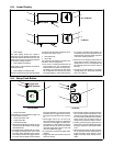
ERR
COM2
ERR
TRG2
ERR
TCH2
ERR
MTR2
Indicates a com-
munication error.
Indicates a trigger
error.
Indicates a
tachometer error.
Indicates a motor
error.
Right Side Motor Control Board PC1
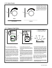
ERR
COM3
Indicates a
communication
error.
Dual Board PC70
2
1
3