


OM-228 322 Page 12
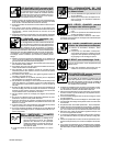
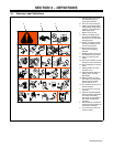
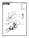
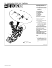
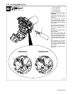
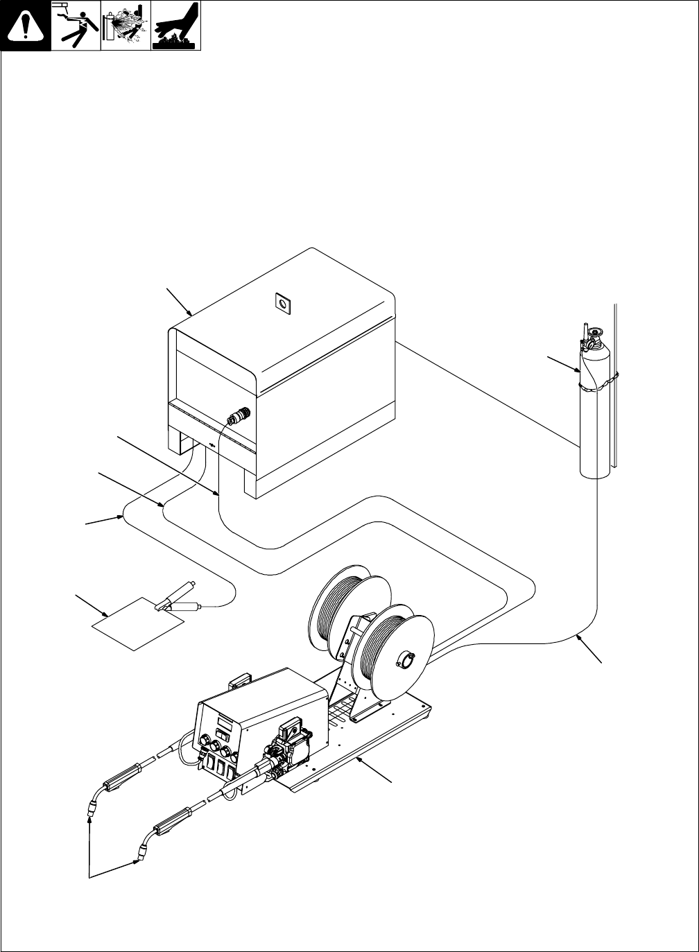
5-2. Equipment Connection Diagrams
1 Welding Power Source
2 Contactor Control/Power Cord
3 Weld Cable
4 Weld Cable
5 Workpiece
6 Welding Gun
7 Wire Feeder
8 Gas Hose
9 Gas Cylinder and Regulator
(Customer Supplied)
. Shielding gas pressure not to
exceed 100 PSI (689 kPa).
804 564-B
1
2
3
4
5
6
7
8
9