


OM-228 322 Page 14
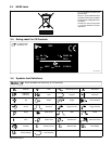
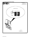
5-4. 14-Pin Plug Information
Pin* Pin Information
A 24 volts ac with respect to socket G.
AJ
K
B Contact closure to A completes 24 volts ac contactor control circuit.
AJ
B
K
I
L
G Circuit common for 24 volts ac circuit.
C
L
NH
D
M
G
C +10 volts dc input from power source to wire feeder with respect to socket D.
D
M
G
E
F
D Remote control circuit common.
E
F
E 0 to +10 volts dc output signal from wire feeder to power source with respect to socket D.
H Voltage feedback; 0 to +10 volts dc, 1 volt per 10 arc volts.
F Current feedback; 0 to +10 volts dc, 1 volt per 100 amperes.
*The remaining pins are not used.
5-5. Gun Recommendation Table
Process Gun
GMAW − Hard or Cored Wires Q-Series Guns: 300, 400, 500,
And 600 Amp.
FCAW − Self-Shielding Wires FC-1260 Or FC-1150
5-6. Wire Type, Size, And Feed Speed Capability Table
Motor Speed Wire Type Wire Size Feed Speed Capability
Standard All .023 To 5/64 in (0.6 To 2 mm) 50 To 1400 ipm (1.3 To 35.6 mpm)
Low All .023 To 1/8 in (0.6 To 3.2 mm) 20 To 400 ipm (0.5 To 10.1 mpm)
1
2
4
3
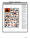
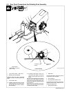
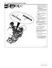
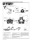
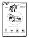
5-7. Installing Drive Rolls
804 187-B
1 Pressure Door Assembly
2 Drive Roll
3 Ejector Button
4 Drive Roll Carrier
Installation
Open pressure door assembly.
Lift drive roll swing arm.
Align drive roll slots with three lobes
on drive roll carrier.
Insert drive roll onto carrier. Drive
roll will snap into place.
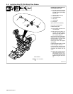
When closing swing arm, push firm-
ly into position.
Swing arm has built in resistance to
prevent swing arm from closing
abruptly.
. When using cored welding wire
use knurled drive rolls.
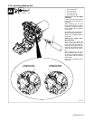
Removal
. Remove PD wire guide before
removing lower drive rolls.
Lift up drive roll swing arm and
press ejector button in middle of
drive roll carrier.