


OM-1600 Page 6
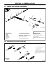
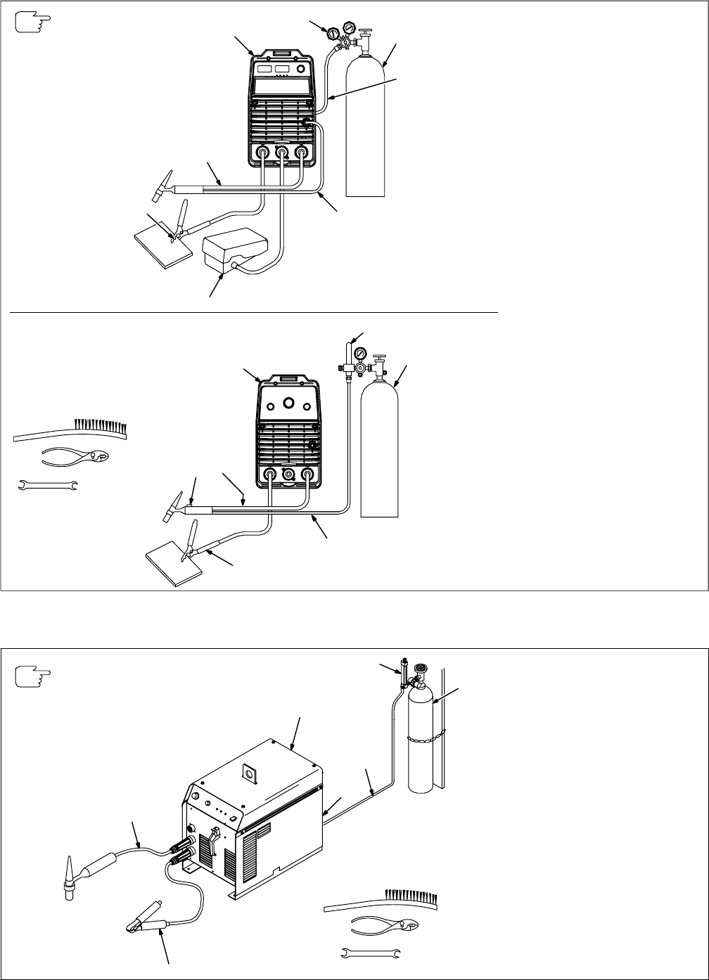
B. Connecting Torch With Two-Piece Cable
803 664-A
Y Turn Off welding power
source power before install-
ing torch.
Obtain the following hose:
1 Gas Hose With 5/8-18 Right-
Hand Fittings
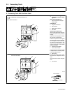
Connections:
2 Regulator/Flowmeter
3 Gas Cylinder
4 Welding Power Source
5 Torch Gas-In Hose
6 Torch Power Cable
7 Work Clamp
Connect work clamp to a clean,
paint-free location on workpiece,
close to weld area.
Use wire brush to clean weld joint
area.
8 Foot Control
9 Gas Valve
Valve controls gas preflow and
postflow. Open valve on torch just
before welding.
Preflow is used to purge the imme-
diate weld area of atomsphere.
Postflow is required to cool tung-
sten and weld, and to prevent con-
tamination of tungsten and weld. Af-
ter welding, leave valve open about
1 second for every 10 amperes of
weld current. Close valve on torch
when postflow is finished.
If applicable, install high-frequency unit.
Tools Needed:
5/8, 7/8 in
Torch With Gas Valve
9
5
6
7
4
2
3
Torch Without Gas Valve
4
2
3
1
6
7
8
5
803 314
−
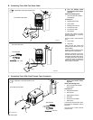
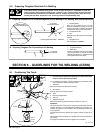
C. Connecting Torch With Flow-Through Type Connection
Y Turn Off welding power
source power before install-
ing torch.
Obtain the following hose:
1 Gas Hose With 5/8-18 Right-
Hand Fittings
Connections:
2 Regulator/Flowmeter
3 Gas Cylinder
4 Welding Power Source
5 Gas Valve
6 One-Piece Torch Cable
7 Work Clamp
Connect work clamp to clean, paint-
free location on workpiece, close to
weld area.
Use wire brush to clean metal at
weld joint area.
Ref. ST-802 540-A
If applicable, install high-frequency unit.
Tools Needed:
5/8, 7/8 in
1
2
3
4
5
6
7
Torch Without Gas Valve