


OM-1600 Page 4
SECTION 3 − INSTALLATION
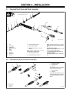
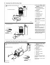
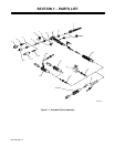
3-1. Required Torch Parts And Torch Assembly
Ref. ST-802 566-B
1 Cup
2 Collet Body
3 Heat Shield
4 Backcap Insulator
5 Collet
6 O-Ring
7 Backcap
8 Torch Body
9 Handle
10 One-Piece Power Cable
11 Power Cable Adapter
12 International Style Flow-Through
Adapter
Note: Adapter needed only if torch is
equipped with one-piece cable.
13 Two-Piece Power Cable
14 International Style Connector
Note: Connector needed only if torch is
equipped with two-piece cable (see Section
3-2).
Assembling Torch Body
Keep connections tight. Replace cup, heat
shield, and backcap as needed.
15 Tungsten Electrode (See Section 5)
Installing Tungsten
To adjust tungsten position, loosen back-
cap.
Assembling Torch Parts
1
2
3
4
11
12
5
7
9
6
15
Or
14
8
10
13
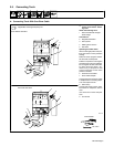
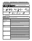
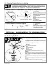
3-2. International Style Connector Assembly
1 Weld Output Cable
2 Insulating Boot
3 Sleeve
Slide insulating boot onto cable;
strip cable and install sleeve.
4 Connector Body
5 Setscrew
Insert cable with sleeve fully into
connector body, tighten setscrew,
and slide insulating boot over con-
nector.
ST-156 496
Tools Needed:
1
2
3
1 in
(26 mm)
3
4
5