


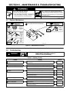
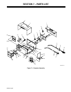

OM-867 Page 3
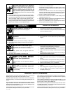
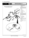
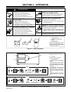
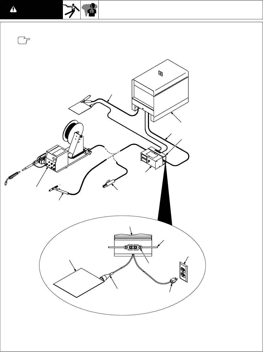
3-2. Connection Diagram
READ SAFETY BLOCKS at start of
Section 3 before proceeding.
WARNING
ST-154 610-B / ST-155 327
1 Welding Power Source
2 Weld Cable (Customer
Supplied)
See power source Owner’s Manual
for proper size cable. Keep cable
length between meter and arc as
short as possible for more accurate
readings.
3 Meter
4 Access Door
5 Shunt Terminal
6 SMAW Electrode Holder
7 GTAW Torch
8 Wire Feeder
Open access door and connect
weld cable from power source to
either shunt terminal. Connect weld
cable from electrode holder, torch
or wire feeder to other shunt termi-
nal.
Close access door.
9 115 VAC Cord/Plug
10 115 VAC Grounded
Receptacle
Connect input power plug to weld-
ing power source or other 115 VAC
receptacle.
11 Voltage Sensing Cord/Clamp
12 Workpiece
Connect voltage sensing clamp to
workpiece.
4
2
5
9
10
11
12
Using meter in applications where high-fre-
quency output is used may cause poor arc
starting and unreliable meter readings.
OR
1
2
4
3
6
7
8
2
Figure 3-2. Connection Diagram