


OM-186 895 Page 11
SECTION 3 − INSTALLATION
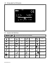
3-1. Specifications
Type of Input
Power
Welding
Power
Source Type
Wire Feed
Speed Range
Wire
Diameter
Range
Welding
Circuit
Rating
IP
Rating
Overall
Dimensions
Weight
24 Volts AC
Single Phase
7 Amperes 50/60
Hz
Constant Voltage
(CV) DC With
14-Pin And
Contactor
Control
1.9 To 19 mpm
(75 to 750 ipm)
0.6 To 2 mm
(.023 To 5/64 in)
Max Spool
Weight:
27 kg (60 lb)
100 Volts,
500 Amperes,
100%
Duty Cycle
IP 23
Length: 597 mm
(23-1/2 in)
Width: 273 mm
(10-3/4 in)
Height: 279 mm
(11 in)
15.9 kg (35 lb)
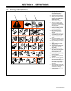
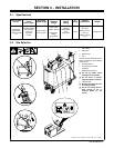
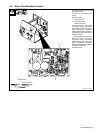
3-2. Site Selection
801 920-C / Ref. 152 468-A / 155 242 / 801 919-C / 188 674
1 Wire Feeder
2 Lifting Eye
3 Rubber Feet
4 Slot
Choose slot that allows all rubber
feet to sit securely on top of welding
power source.
5 Wire Spool/Reel
6 Gas Cylinder (Customer
Supplied)
7 Welding Power Source
Y Do not put feeder where
welding wire hits cylinder.
Y Do not move or operate
equipment when it could tip.
8 Lifting Handle
Y Manually use handle to move
or briefly lift feeder.
Y Do not use lifting hook or
other devices to lift or
suspend feeder by the
handle.
2
4
3
1
56
7
8