


.A complete Parts List is available at www.MillerWelds.com
OM-232 386 Page 13
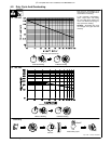
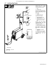
4-3. Volt-Ampere Curves
The volt-ampere curves show the
minimum and maximum voltage
and amperage output capabilities of
the welding power source. Curves
of other settings fall between the
curves shown.
.Ranges 4, 5, and 6 apply to 230
VAC only.
ssb1.1 10/91 − 199 212
0
5
10
15
20
25
30
35
0 50 100 150 200 250
DC AMPERES
DC VOLTS
Range 1
Range 2
Range 3
Range 4
Range 5
Range 6
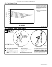
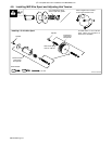
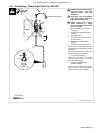
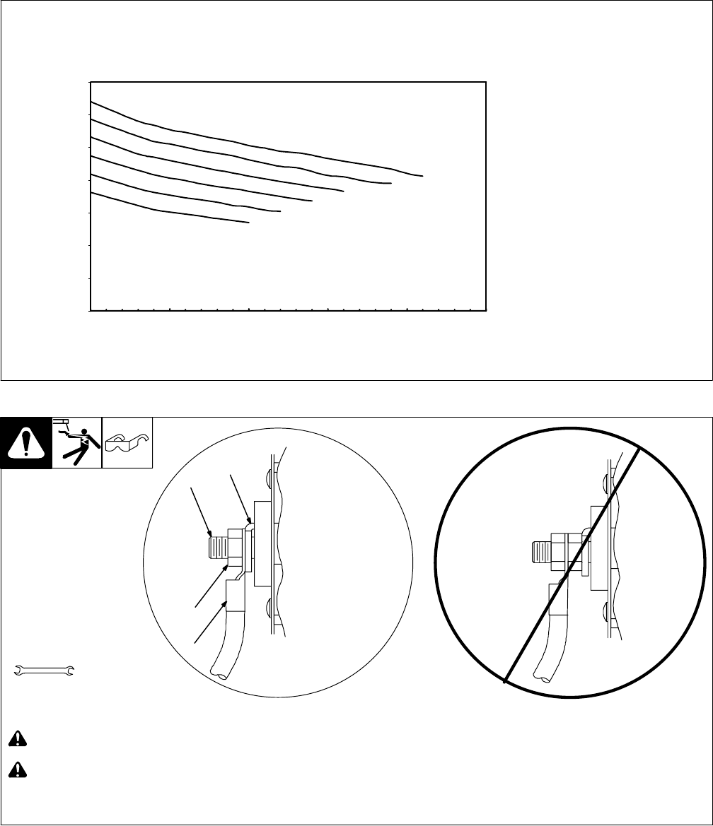
4-4. Connecting To Weld Output Terminals
803 778-A
! Turn off power before connecting to
weld output terminals.
! Failure to properly connect weld
cables may cause excessive heat
and start a fire, or damage your ma-
chine.
1 Weld Output Terminal
2 Supplied Weld Output Terminal Nut
3 Weld Cable Terminal
4 Copper Bar
Remove supplied nut from weld output ter-
minal. Slide weld cable terminal onto weld
output terminal and secure with nut so that
weld cable terminal is tight against copper
bar. Do not place anything between weld
cable terminal and copper bar. Make
sure that the surfaces of the weld cable
terminal and copper bar are clean.
Tools Needed:
3/4 in (19 mm)
4
2
3
Do not place
anything between
Correct Installation
Incorrect Installation
1
weld cable terminal
and copper bar.