


OM-1330 Page 20
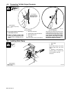
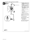
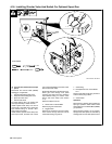
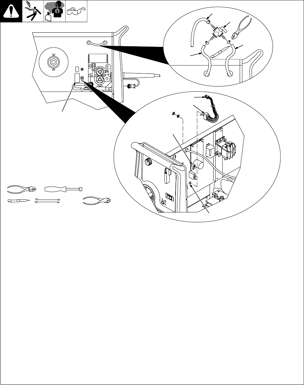
4-16. Installing Diverter Valve And Switch For Optional Spool Gun
Ref. 803 906-B / 803 908-A
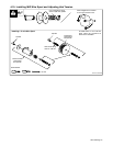
Tools Needed:
Y Turn Off unit, and disconnect input
power.
Disconnect and remove MIG (GMAW)
welding gun, if applicable.
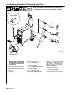
1 Input End Of Existing Gas Hose
2 Output End Of Existing Gas Hose
3 Spool Gun Gas Hose
4 Gas Diverter Valve
To install diverter valve, cut existing gas
hose approximately in middle of hose.
Install supplied hose clamp onto end of
output hose, and slide end of hose onto
input barbed fitting on diverter valve.
Secure with hose clamp.
Install another supplied hose clamp onto
end of input hose, and slide end of hose
onto output barbed fitting on diverter valve.
Secure with hose clamp.
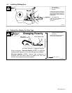
Slide hose clamp down gas hose from gun.
Route gas hose through front panel
opening, and slide hose onto remaining
output barbed fitting on diverter valve.
Secure with hose clamp (see Section
4-17).
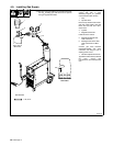
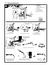
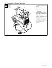
Remove wrapper from unit.
5 Switch Hole In Center Baffle
Remove plug from switch hole.
6 Toggle Switch
Remove nut and locking ring from switch.
Insert switch through hole and secure
switch with locking ring and nut.
7 Switch Plug
8 Receptacle RC4 On Circuit Board
PC1
Remove and retain jumper plug from RC4.
Connect switch plug to RC4.
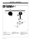
9 Switch Label
Operation:
Place switch in SPOOL GUN position for
spool gun operation. Place switch in MIG
GUN position for wire feeder/MIG (GMAW)
gun operation.
When spoolgun switch is in On position,
spoolgun wire feed speed is controlled by
welding power source Wire Speed control.
9
1
2
3
4
5
7
6
8
1/4 in
9/16 in