


OM-808 Page 12
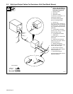
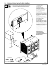
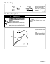
3-3. Weld Input/Output Cables For Resistance Grid (Dual Model Shown)
Y Turn Off welding power
source, and disconnect in-
put power before making any
weld output connections.
1 Weld Input Cable
2 Work Cable
3 Weld Output Cable
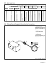
If necessary, use Section 3-7 to
select proper cable size.
Use shortest cables possible.
Do not use damaged cables.
4 Terminal Lug
Use lugs of proper amperage ca-
pacity and hole size for connecting
to common work, electrode hold-
er(s), and weld output terminals (if
applicable).
5 Common Work Connection
Connect work cable to common
work according to codes.
6 Insulated Electrode Holder
7 GTAW Torch
Install according to manufacturer’s
instructions.
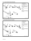
8 Female Camlok Connector
Install onto weld input cable as
shown in Section 3-5.
9 Weld Input Receptacle
Connect cable to weld input recep-
tacle on rear panel of grid.
10 Male Camlok Connector
Install onto weld output cable as
shown in Section 3-6.
11 Electrode Receptacle
Connect electrode holder cable to
Electrode receptacle.
S-0793
Tools Needed:
Or
3
4
67
8
10
4
1
5
2
11
8
9