


OM-808 Page 19
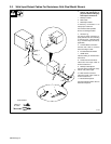
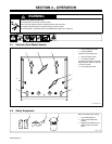
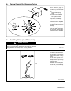
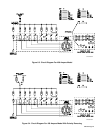
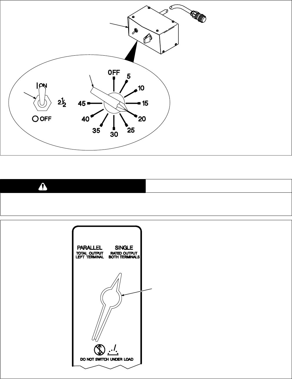
4-6. Optional Remote Grid Amperage Control
ST-080 370-A / Ref. ST-122 903-D
Remote amperage control only
works when Fine Amperage control
and optional 2-1/2 Ampere switch
are in the Off position (see Section
4-5).
1 Remote Grid Amperage
Control
See Section 3-8 for installation.
2 Fine Amperage Control
Use control to add amperage, in 5
ampere steps, to weld output.
For front panel amperage adjust-
ment, place control in Off position.
3 2-1/2 Ampere Switch
Use switch to add 2-1/2 amperes to
weld output.
To add 2-1/2 amperes to weld
output, place switch in On position.
For front panel amperage adjust-
ment, place control in Off position.
3
2
1
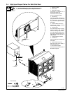
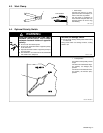
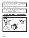
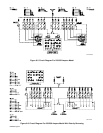
4-7. Paralleling Switch (Dual Models Only)
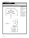
CAUTION
ARCING can damage switch.
• Do not change Paralleling switch position while welding or under load.
Arcing inside switch can damage contacts, causing switch to fail.
warn5.1* 2/93
Ref. ST-122 903-D
1 Paralleling Switch
Use switch to select weld output at
one or both Electrode terminals.
For weld output at both Electrode
terminals, place switch in Single
position.
For total weld output at the left
Electrode terminal, place switch in
Parallel position. Output at the right
terminal is 0 (zero).
When switch is in Parallel position,
all front panel amperage controls
(left and right) adjust weld output
(see Section 4-5).
1