


OM-1102 Page 1
SECTION 1 – SAFETY PRECAUTIONS AND SIGNAL WORDS
1-1. GENERAL INFORMATION AND SAFETY
A. General
Information presented in this manual and on various la-
bels, tags, and plates on the unit pertains to equipment
design, installation, operation, maintenance, and
troubleshooting which should be read, understood, and
followed for the safe and effective use of this equipment.
B. Safety
The installation, operation, maintenance, and trouble-
shooting of arc welding equipment requires practices
and procedures which ensure personal safety and the
safety of others. Therefore, this equipment is to be in-
stalled, operated, and maintained only by qualified per-
sons in accordance with this manual and all safety pre-
cautions in the welding power source Owner’s Manual.
1-2. SAFETY ALERT SYMBOL AND SIGNAL
WORDS
The following safety alert symbol and signal words are
used throughout this manual to call attention to and
identify different levels of hazard and special instruc-
tions.
This safety alert symbol is used with the signal
words WARNING and CAUTION to call atten-
tion to the safety statements.
WARNING statements identify procedures or
practices which must be followed to avoid seri-
ous personal injury or loss of life.
CAUTION statements identify procedures or
practices which must be followed to avoid minor
personal injury or damage to this equipment.
IMPORTANT statements identify special instructions
necessary for the most efficient operation of this equip-
ment.
SECTION 2 – SPECIFICATIONS
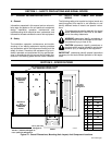
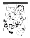
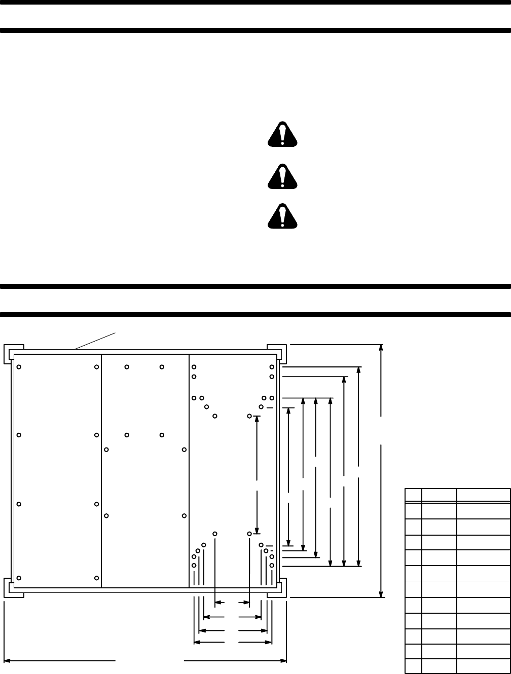
**65 in. (1651 mm)
Swingpak-12
Gas Cylinder Support Bracket Located
Here (SWINGPAK-12 Models Only)
G
H
J
Coolant System
(Mounted Onto
SWINGPAK
Locker)
Resistance
Grid
(Mounted Onto
SWINGPAK
Locker)
Flux
Tank
Boom
Support
Base
Welding
Power
Source
FRONT
A
B
C
D
E
F
*50-7/8 in.
(1292 mm)
Swingpak-12
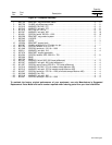
Inches Millimeters
A
B
C
D
E
F
G
H
J
28
30
31
32-3/4
37
39
14-1/2
16-3/4
20
711
762
787
831
940
991
368
415
508
*66-7/8 in. (1699 mm) Swingpak-16
**79 in. (2007 mm) Swingpak-16
S-0458-A
K
L
K 12-3/8 314
L 24-1/16 611
Figure 2-1. Overall Dimensions, Mounting Hole Layout, And Component Locations