


OM-1102 Page 2
2-1. DESCRIPTION
The SWINGPAK-12 and SWINGPAK-16 provide a di-
rect mounting facility for several welding power sources
(refer to welding power source Owner’s Manual for base
mounting hole layout), SWINGARC wire feeder or CB
boom, RADIATOR 1A or RADIATOR 2A coolant sys-
tem, MPG-395B resistance grid, AFT-100 flux tank, and
shielding gas cylinder. If equipment other than that listed
is to be used, mounting hole locations may have to be
modified to accommodate equipment. A SWINGPAK
locker and brackets for mounting a disconnect switch to
the SWINGARC post support are also supplied.
Additional space is available on the base for mounting
customer supplied accessories.
Table 2-1. Specifications
Weight
Net Ship
SWINGPAK-12
SWINGPAK-16
412 lbs.
(187 kg)
504 lbs.
(229 kg)
418 lbs.
(190 kg)
510 lbs.
(231 kg)
SECTION 3 – INSTALLATION OR RELOCATION
WARNING: ELECTRIC SHOCK can kill.
• Do not touch live electrical parts.
• Disconnect equipment input power conduc-
tors from deenergized supply line BEFORE
moving unit.
3-1. LOCATION
When installing this unit, be sure to allow room for the
boom to swing horizontally in the desired arc, and to piv-
ot upward to the desired angle. The location should al-
low room to remove panels of associated equipment for
installation, inspection, maintenance, and repair proce-
dures. Consider the input power requirements as well as
coolant (water) needs of optional equipment when
choosing a location.
The service life and efficiency of this unit and associated
equipment will be reduced if they are subjected to high
levels of dust, dirt, moisture, corrosive vapors, and ex-
treme heat.
Mounting holes are provided in the SWINGPAK base for
installing equipment.
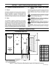
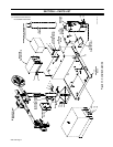
3-2. INSTALLATION (Figures 2-1 And 4-1)
WARNING: OVERTURNING BASE can result
in serious injury and equipment damage.
• Mount the welding power source on SWING-
PAK base before mounting SWINGARC wire
feeder into SWINGARC support base.
• Do not install or operate on an incline.
• Do not lift the SWINGPAK base with a fork lift
from the sides unless the lift forks extend far
enough under the base to ensure against tip-
ping.
IMPROPER LIFTING OR INSTALLING OF
EQUIPMENT can cause personal injury and
equipment damage.
• Use equipment of adequate capacity to lift
components.
• Use bolts and fasteners of adequate capacity
to assemble and install unit.
IMPORTANT: Refer to Figures 2-1 and 4-1 during as-
sembly as necessary.
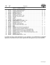
Mounting hardware is packed in locker for shipping pur-
poses. Remove hardware kit from locker and proceed
as follows:
1. Install boom support base onto SWINGPAK base
using supplied 1/2-13 x 1-1/2 inch cap screws
(Item 23, Figure 4-1) and associated hardware
(see Figure 2-1 for mounting location).
2. Locate appropriate mounting holes on SWING-
PAK base for welding power source, and install
power source onto SWINGPAK base using
supplied 3/8-16 x 1-1/4 inch cap screws (Item 20,
Figure 4-1).
3. Install boom into boom support base following
procedure outlined in appropriate Owner’s Manu-
al.
4. If applicable, install AFT-100 flux tank onto
SWINGPAK base using supplied 5/16-18 x 1 inch
cap screws (Item 13, Figure 4-1) and associated
hardware.
5. Install SWINGPAK locker onto SWINGPAK base
using supplied 1/4-20 x 3/4 inch self-threading
screws (item 16, Figure 4-1).
6. If applicable, install coolant system mounting
brackets onto SWINGPAK locker using supplied
1/4-20 x 1inch cap screws (Item 7, Figure 4-1).