


OM-225 Page 13
L1
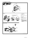
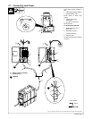
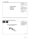
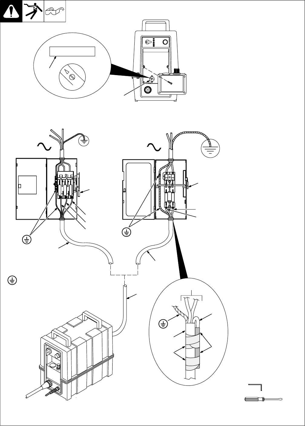
2-7. Connecting Input Power
input_2 – 3/96 / Ref. ST-144 221 / Ref. ST-070 399-C / Ref. ST-801 390 / ST-801 392
Check input voltage available at
site.
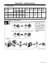
1 Input Voltage Selector Switch
2 Selector Switch Label
Rotate switch to match input
voltage.
3 Input And Grounding
Conductors
4 Line Disconnect Device
See Section 2-6.
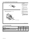
For single-phase operation:
5 Black And Brown Input
Conductor
6 Blue Input Conductor
7 Insulation Sleeving
8 Electrical Tape
Insulate and isolate blue conductor
as shown.
4
4
3
3
3
5
3
8
7
6
L2
L3
L1
L2
Y Always connect grounding
conductor first.
1
3
= GND/PE
Tools Needed:
1
2
5/32 in
230 460