


OM-229 038 Page 11
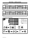
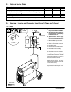
3-7. Electrical Service Guide
Migmatic Model
221 253
Input Voltage
220/230 230 400
Input Amperes at Rated Output
26 23 13
Max Recommended Standard Fuse or Circuit Breaker Rating in Amperes
26 23 13
** Input Conductor Size in mm
2
4 4 4
** Grounding Conductor Size in mm
2
4 4 4
** Power cord supplied with the unit is sized for 230V operation. Larger power cord may be required for cable lengths greater than 3 meters.
Consult national and local regulations.
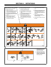
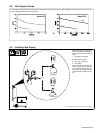
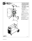
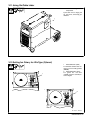
3-8. Selecting a Location and Connecting Input Power (1-Phase and 3-Phase)
A. 1-Phase
803 766-B
Y Installation must meet all National
and Local Codes − have only quali-
fied persons make this installation.
Y Disconnect and lockout/tagout in-
put power before connecting input
conductors from unit.
Y Always connect green or green/
yellow conductor to supply
grounding terminal first, and never
to a line terminal.
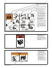
1 Black And White Input Conductor
(L1 And L2)
2 Green Or Green/Yellow Grounding
Conductor
3 Input Power Cord.
4 Disconnect Device (switch shown in
the OFF position)
5 Disconnect Device Grounding
Terminal
6 Disconnect Device Line Terminals
Connect green or green/yellow grounding
conductor to disconnect device grounding
terminal first.
Connect input conductors L1 and L2 to
disconnect device line terminals.
7 Over-Current Protection
Select type and size of over-current
protection using Section 3-7 (fused dis-
connect switch shown).
Close and secure door on disconnect
device. Remove lockout/tagout device,
and place switch in the On position.
4
3
L1
L2
1
=GND/PE
Earth Ground
2
1
5
6
7
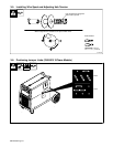
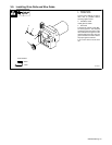
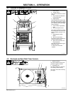
Tools Needed:
18 in (457 mm)
for airflow