


OM-494 Page 68
Description
Part
No.
Dia.
Mkgs.
Item
No.
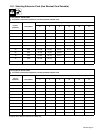
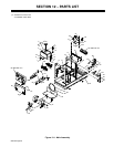
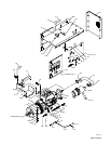
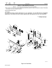
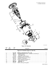
Figure 12-4. Generator (Continued)
Quantity
13 195 704 STATOR, exciter aux pwr 120/240 1. . . . . . . . . . . . . . . . . . . . . . . . . . . . . . . . . . . . . . . . . . . . . . . . . .
14 173 068 ENDBELL, generator (consisting of) 1. . . . . . . . . . . . . . . . . . . . . . . . . . . . . . . . . . . . . . . . . . . . . . . . .
15 143 220 O-RING 2.859ID x .139CS 1. . . . . . . . . . . . . . . . . . . . . . . . . . . . . . . . . . . . . . . . . . . . . . . . . . . . . . . . .
+When ordering a component originally displaying a precautionary label, the label should also be ordered. Order label
individually or as part of Label Kit 193 501
*Recommended Spare Parts.
To maintain the factory original performance of your equipment, use only Manufacturer’s Suggested
Replacement Parts. Model and serial number required when ordering parts from your local distributor.
. Hardware is common and
not available unless listed.
802 319
1
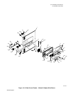
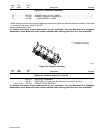
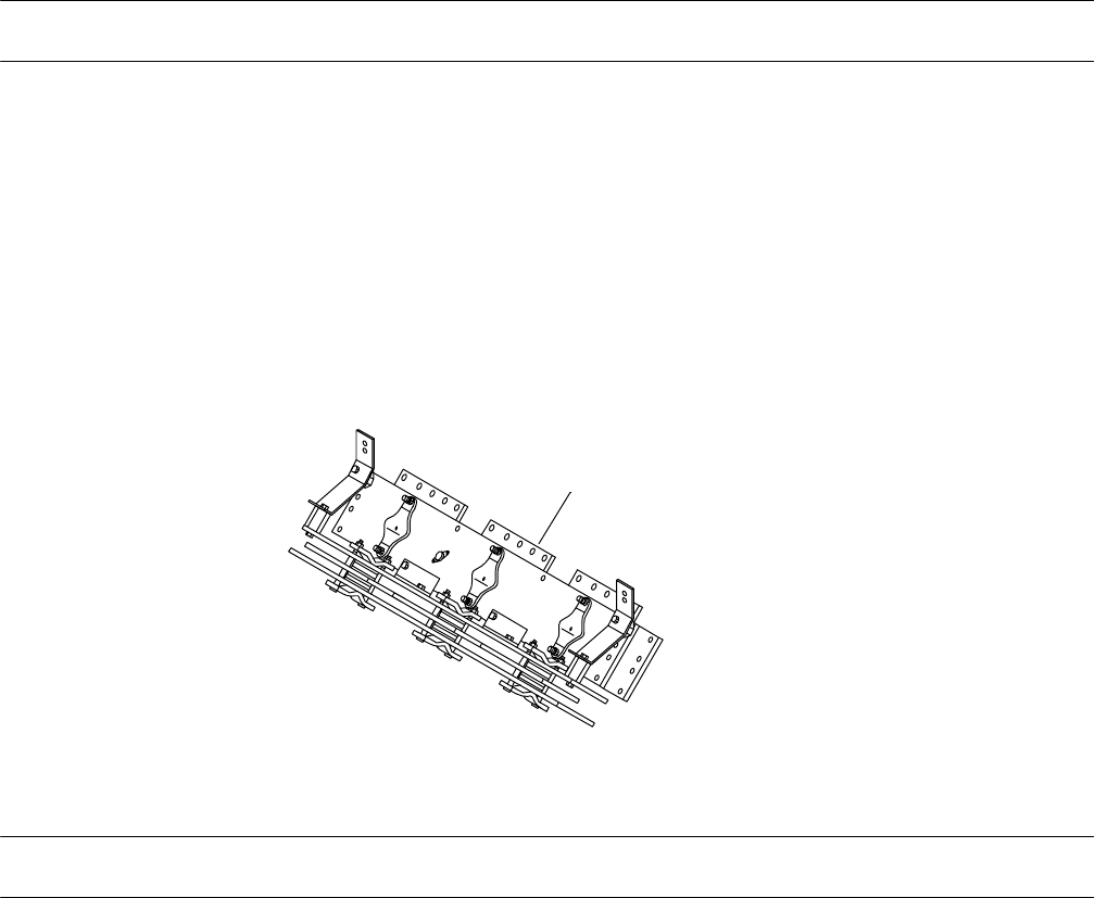
Figure 12-5. Rectifier Assembly
Description
Part
No.
Dia.
Mkgs.
Item
No.
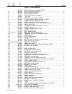
Figure 12-5. Rectifier (Figure 12-1 Item 25)
Quantity
1 205 613 RECTIFIER ASSEMBLY 1. . . . . . . . . . . . . . . . . . . . . . . . . . . . . . . . . . . . . . . . . . . . . . . . . . . . . . . . . . . .
203 001 RECTIFIER, Si Diode (One Side Service kit W/Varnish Coating) 1. . . . . . . . . . . . . . . . . . . . . . . . . . . .
PLG1, PLG2 158 720 CONNECTOR & SOCKETS 1. . . . . . . . . . . . . . . . . . . . . . . . . . . . . . . . . . . . . . . . . . . . . . . .
To maintain the factory original performance of your equipment, use only Manufacturer’s Suggested
Replacement Parts. Model and serial number required when ordering parts from your local distributor.