


OM-228 305 Page 14
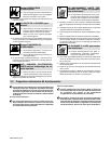
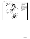
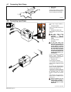
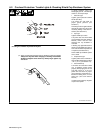
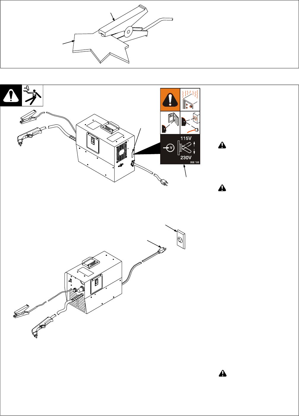
4-7. Connecting Work Clamp
802 463-A
1 Work Clamp
2 Workpiece
Connect work clamp to a clean,
paint-free location on workpiece, as
close to cutting area as possible.
1
2
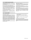
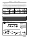
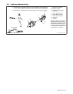
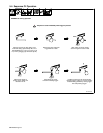
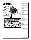
4-8. Connecting Input Power
Ref. 802 787-A / 804 488-A
Check input voltage available at
site.
1 Changeover Switch
Switch is accessible through slot in
rear panel.
2 Changeover Switch Label
Look at label to find correct switch
position.
! Be sure input power
connection meets all
applicable national,
regional, and local electrical
codes.
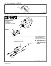
3 Grounded 120 VAC
Receptacle
! To use rated output (see
specifications), connect the
unit to an individual branch
circuit capable of carrying
the effective (eff) current for
the output being used. The
unit must have a properly
sized plug installed and the
circuit must be protected by
properly sized fuses or cir-
cuit breakers.
A 120 volt, 20 ampere individual
branch circuit protected by
time-delay fuses or circuit breaker
is required (see Section 4-1).
4 Plug From Unit
Connect plug to receptacle.
If an extension cord is necessary,
select a cord of 12 AWG for up to 53
ft (16 m).
To connect unit to 230 VAC input
power, a customer supplied plug is
necessary (see Section 4-9).
A 230 volt, 15 ampere (minimum)
individual branch circuit protected
by time-delay fuses or circuit
breaker is required (see Section
4-1).
If an extension cord is necessary,
select a cord of 14 AWG for up to
133 ft (41 m).
! Special installation may be
required where gasoline or
volatile liquids are present −
see NEC Article 511 or CEC
Section 20.
2
1
4
3