


OM-228 305 Page 21
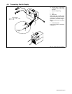
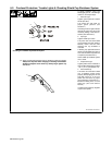
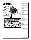
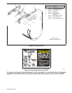
6-3. Torch And Work Cable Connections
If torch or work cable needs to be
removed or replaced, proceed as
follows:
Turn power Off, and disconnect
input power plug from receptacle.
Remove wrapper from unit.
Torch Connections
Remove existing torch cable from
unit.
1 Strain Relief
2 Torch Cable
Insert cable through strain relief.
Slide strain relief nut onto torch
cable, but do not tighten.
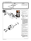
3 Air Line Connector
Insert air line connector into
solenoid fitting.
4 Plug PLG1/Receptacle RC1
Connect PLG1 from torch to
receptacle RC1 on end of wiring
harness connected to circuit board
PC1.
5 Ring Terminal And TORCH
RED Terminal
Connect ring terminal on end of red
leads to TORCH RED terminal.
6 Ring Terminal And TORCH
WHITE Terminal
Connect ring terminal on end of
white leads to TORCH WHITE
terminal.
Tighten strain relief nut.
Tighten strain relief around cable.
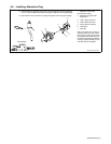
Work Cable Connections
Remove existing work cable from
unit.
7 Work Cable
. Be sure to allow some work
cable slack inside the unit.
Insert work cable with strain relief
into front panel.
Tighten strain relief nut. Tighten
strain relief around cable.
8 Work Cable Ring Terminal
Route cable under center baffle.
Connect ring terminal on end of
work cable to terminal labeled
WORK on circuit board PC1.
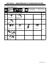
Tools Needed:
804 489-B / Ref. 802 860 / 226 678-C
3
2
4
6
5
1/4 in
3
4
2
7
5
8
6
1
4
86 5