


OM-4422 Page 40
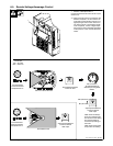
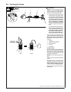
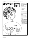
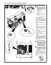
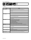
8-9. Adjusting Engine Speed On Models With Automatic Idle (Optional)
803 563-G
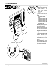
Engine Speed Adjustment
After tuning engine, check engine
speed with tachometer or frequen-
cy meter. See table for proper no
load speed. If necessary, adjust
speed as follows:
Start engine and run until warm.
Turn Process/Contactor switch to
Stick − Weld Terminals Always On
position.
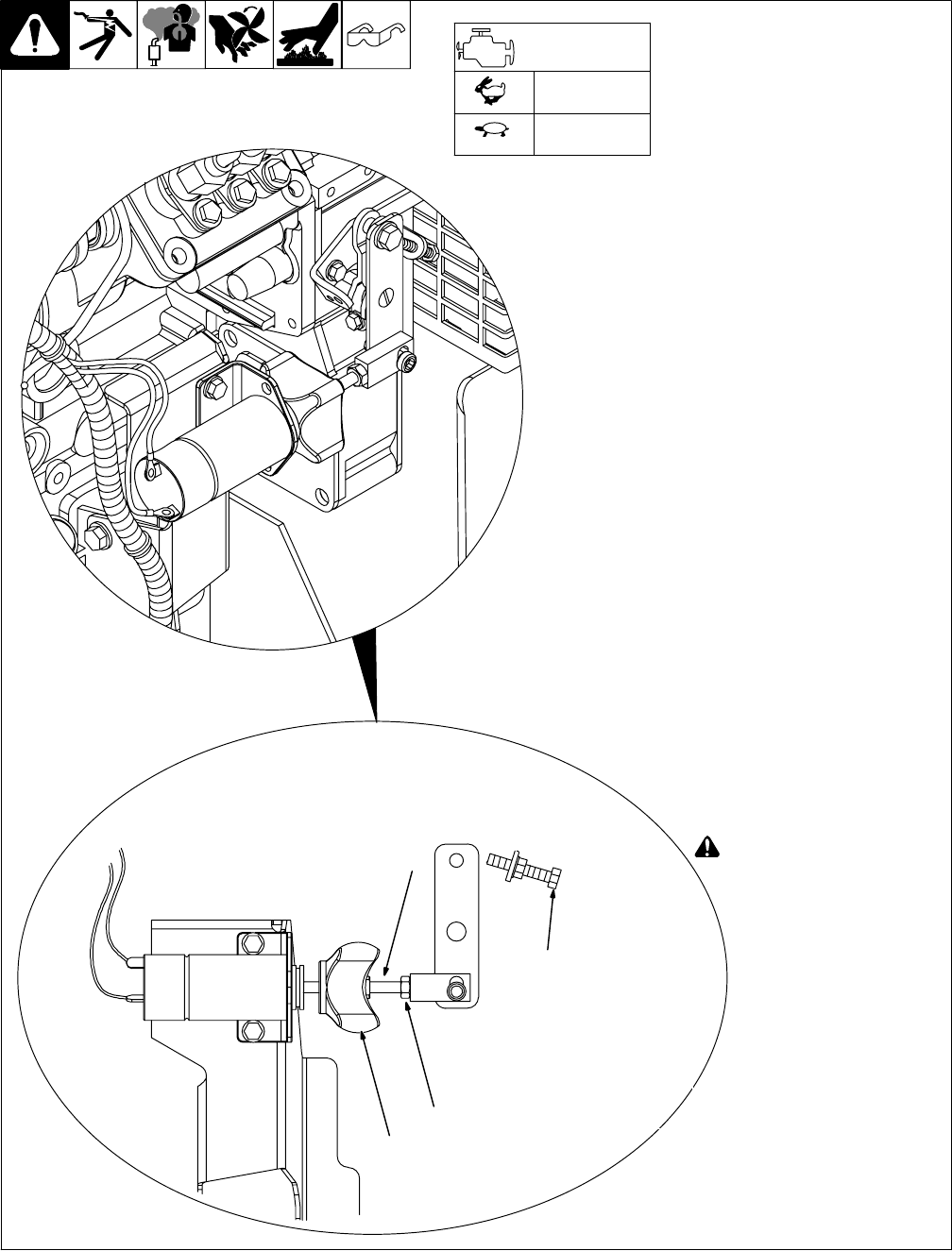
1 Throttle Rod / Plunger
2 Lock Nut
3 Rubber Boot
4 Adjustment Screw
Adjustment screw is not used to ad-
just engine speed when automatic
idle option is installed. However, it
must be at least 1/8 in (3 mm) away
from the throttle arm when engine is
running at idle rpm.
Unhook rubber boot from the sole-
noid housing but leave connected
to plunger.
Loosen lock nut. Place Engine
Control Switch in Auto position.
Turn throttle rod and plunger until
engine runs at idle speed. Tighten
lock nut.
Hook rubber boot back onto sole-
noid housing.
. Be sure solenoid plunger pulls
all the way in (“bottoms”) when
energized.
Weld/Power Speed Adjustment
. Weld/power speed adjustment
must be done by the engine
manufacturer’s factory autho-
rized service agent.
Tampering with adjustments
other than shown may affect
engine warranty.
! Stop engine.
1
1880 rpm max
(62.6 Hz)
1500 rpm
(50 Hz)
Engine Speed
(No Load)
2
3
4
. To prevent solenoid
damage, be sure a 1/8
in (3 mm) gap exists be-
tween the engine low
speed screw and
throttle lever when the
solenoid is held in the
energized position.