


OM-202 515 Page 15
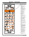
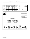
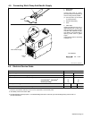
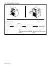
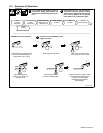
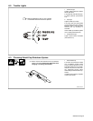
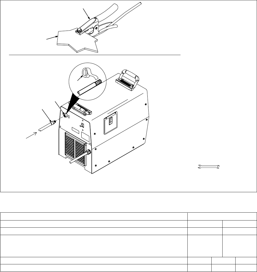
4-5. Connecting Work Clamp And Gas/Air Supply
Ref. 803 640-A / 802 803-A
1 Work Clamp
2 Workpiece
Connect work clamp to a clean,
paint-free location on workpiece, as
close to cutting area as possible.
. Use only clean, dry air with 90
to 150 psi pressure.
3 Gas/Air Inlet Opening
4 Hose
5 Teflon Tape
Obtain hose with 3/8 in (9.5 mm) or
larger diameter and 1/4 NPT right-
hand thread fitting. Wrap threads
with teflon tape (optional) or apply
pipe sealant, and install fitting in
opening. Route hose to gas/air
supply.
Adjust gas/air pressure according
to Section 5-2.
Tools Needed:
5/8, 1-1/8 in
From Gas/Air Supply
3
4
Rear of
Unit
5
1
2
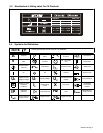
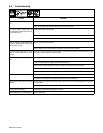
4-6. Electrical Service Guide
Max Recommended Standard Fuse Rating In Amperes
Input Voltage
Input Amperes At Rated Cutting Capacity
Circuit Breaker
1
, Time-Delay
2
Normal Operating
3
UPC 838
380 440
21.6 19.3
30 30
35 35
4610
50 100 150
Min Input/Grounding Conductor Size In mm
2
Max Recommended Input Conductor Length In Meters
Reference: 1999 National Electrical Code (NEC)
1 Choose a circuit breaker with time-current curves comparable to a Time Delay Fuse.
2 “Time-Delay” fuses are UL class “RK5” .
3 “Normal Operating” (general purpose − no intentional delay) fuses are UL class “K5” (up to and including 60 amp), and UL class “H”
( 65 amp and above).