


OM-202 515 Page 17
SECTION 5 − OPERATION
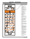
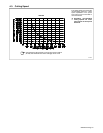
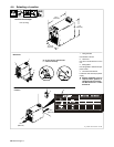
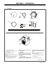
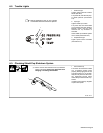
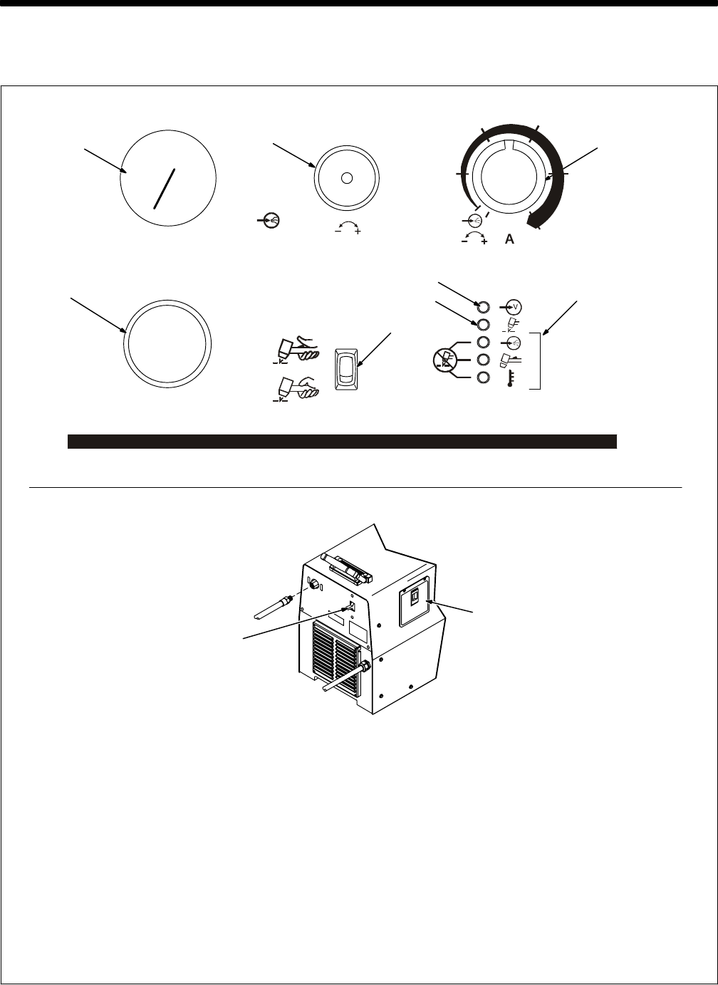
1 Gas/Air Pressure Gauge
2 Gas/Air Pressure Adjustment Knob
3 Output Control
Use control to set cutting output.
Gas/air automatically flows at the set
pressure.
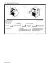
Use Gas/Air Set area of control range for set-
ting gas/air pressure (see Section 5-2).
4 Trouble Lights (see Section 6-2)
Power light comes On when Power switch is
placed in On position.
5 Power Light
6 Ready Light
Ready light comes On when unit is On to indi-
cate that all safety shutdown systems are
okay. If Ready light does not come On, check
trouble lights.
7 Trigger Hold Switch
To cut without holding torch trigger, set trigger
hold switch so upper end is pressed In. Press
the torch trigger, begin cutting, and release
the trigger. To stop cutting, press and release
trigger.
When set in down position, trigger must be
held closed while cutting.
8 Torch Quick-Disconnect Connector
9 Power Switch
10 Door for Consumables Storage
5-1. Controls
Ref. 202 359 / Ref. 802 803-A
10
9
Rear of
Unit
8
1
2
7
4
5
6
3
80
70
60
50
40