


OM-215 092 Page 6
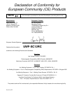
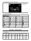
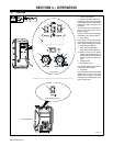
2-2. Manufacturer’s Rating Label For CE Products
For label location
see Section 4-1.
S/N:
24
10.0
Hz50/60
IP 23
V100 A500 X 100 %
MILLER ELECTRIC MFG. CO., APPLETON, WI USA
V
U
1
=
A
I
1
=
1
U
2
=
I
2
=
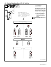
2-3. Symbols And Definitions
Some symbols are found only on CE products.
NOTE
Output Input
A
Amperes
V
Volts
X
Duty Cycle Wire Feed Percent
IP
Degree Of Protec-
tion
Input
Cold Jog (Inch) To-
wards Workpiece
Purge By Gas Fast
Constant Current Circuit Breaker Constant Voltage Slow
Trigger Hold Off Trigger Hold On
I
2
Rated Welding
Current
Increase
Read Instructions
U
1
Primary Voltage
U
2
Conventional Load
Voltage Hz
Hertz
I
1
Primary Current
SECTION 3 − INSTALLATION
3-1. Specifications
Type of
Input
Power
Welding
Power
Source
Type
Wire Feed
Speed
Range
Wire
Diameter
Range
Input
Welding
Circuit
Rating
IP
Rating
Max. Wire
Spool
Capacity
Overall
Dimensions
Weight
24 Volts AC
Single Phase
10 Amperes
50/60 Hz
Constant
Voltage (CV)
DC With
14-Pin And
Contactor
Control
50 to 700 ipm
(1.3 To 17.8
mpm)
.023 To 5/64 in
(0.6 To 2 mm)
100 Volts,
500
Amperes,
100%
Duty Cycle
23
30 lb (13.6
kg),
12 in (304
mm)
Length: 20 in
(508 mm)
Width: 8 in
(203 mm)
Height: 15-1/2 in
(394 mm)
25.5 lb
(11.6 kg)