


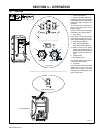
OM-215 092 Page 7
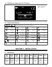
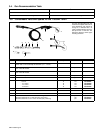
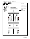
3-2. 14-Pin Plug Information
Pin* Pin Information
A 24 volts ac with respect to socket G.
AJ
K
B Contact closure to A completes 24 volts ac contactor control circuit.
AJ
B
K
I
L
G Circuit common for 24 volts AC circuit.
C
L
NH
D
M
G
C +10 volts dc input from power source to wire feeder with respect to socket D.
D
M
G
E
F
D Remote control circuit common.
E
F
E 0 to +10 volts dc output signal from wire feeder to power source with respect to socket D.
H Voltage feedback; 0 to +10 volts dc, 1 volt per 10 arc volts.
F Current feedback; 0 to +10 volts dc, 1 volt per 100 amperes.
*The remaining pins are not used.
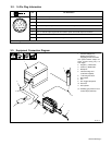
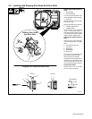
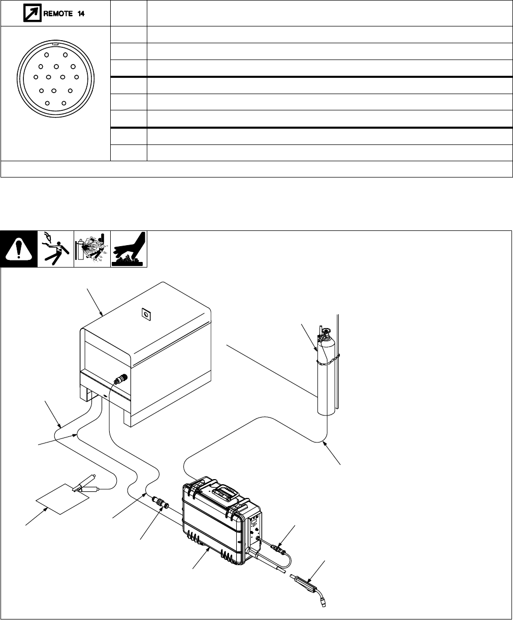
3-3. Equipment Connection Diagram
804 207-A
1 Constant Voltage (CV)
Welding Power Source
Supplying 24 VAC To Feeder
Use optional PSA-2 adapter for
power sources having only 115
VAC supply.
2 Negative (−) Weld Cable
3 Positive (+) Weld Cable
4 Workpiece
5 Interconnecting Cord
(Customer Supplied)
6 14-Pin Plug And Cord
7 Wire Feeder
8 Gun
9 Gun Trigger Receptacle
10 Gas Hose
11 Gas Cylinder
. Shielding gas pressure not to
exceed 90 psi (620 kPa).
1
2
3
4
5
6
7
8
9
10
11