


OM-1078 Page 9
SECTION 3 − INSTALLATION
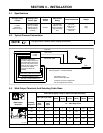
3-1. Specifications
AC Input Power
1-Phase
Welding Power
Source Type
DC Output For
Control
Circuit
Weld Circuit
Rating
Overall Dimensions Weight
115 Volts,
2 Amperes,
50/60 Or 100 Hz
Constant Current
(CC) Or Constant
Voltage (CV) DC,
With Or Without
Contactor
30 Volts
100 Volts, 200
Amperes, 100%
Duty Cycle Using
Argon Shielding
Gas
Length: 12-1/4 in
(311 mm)
Width: 9-1/4 in
(235 mm)
Height: 8-5/8 in
(219 mm)
20 lb
(9 kg)
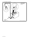
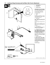
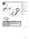
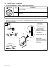
3-2. Typical Process Connections
Use gun Owner’s Manual when making connections.
NOTE
Constant current and/or
constant voltage transformer
and engine-driven DC power
sources. If the power source
does not have a weld output
contactor, the optional
contactor kit should be
ordered.
Work
Voltage Sensing Lead For CC Mode
(Factory Supplied − Customer Installed)
Gas Hose
Control Cord
115 Volt
Control
Weld Power Cable
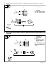
Weld Power Cable* (Not Included)
10 ft (3 m) Contactor Cord**
10 ft (3 m) 115 VAC Power Cord
**Contactor cord only supplied with
unit not equipped with contactor.
*See Section 3-3 for
recommended cable sizes.
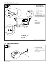
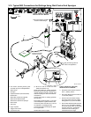
3-3. Weld Output Terminals And Selecting Cable Sizes
Total Cable (Copper) Length In Weld Circuit Not Exceeding
100 ft (30 m) Or Less
150 ft
(45 m)
200 ft
(60 m)
250 ft
(70 m)
300 ft
(90 m)
350 ft
(105 m)
400 ft
(120 m)
Weld Output
Terminals
Welding
Amperes
10 − 60%
Duty
Cycle
60 − 100%
Duty
Cycle
10 − 100% Duty Cycle
100 4 4 4 3 2 1 1/0 1/0
150 3 3 2 1 1/0 2/0 3/0 3/0
200 3 2 1 1/0 2/0 3/0 4/0 4/0
250 2 1 1/0 2/0 3/0 4/0 2-2/0 2-2/0
801 487-A
300 1 1/0 2/0 3/0 4/0 2-2/0 2-3/0 2-3/0
Weld cable size (AWG) is based on either a 4 volts or less drop or a current density of at least 300 circular mils per ampere. S-0007-D