


OM-1078 Page 11
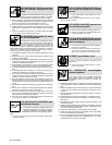
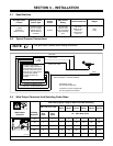
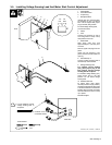
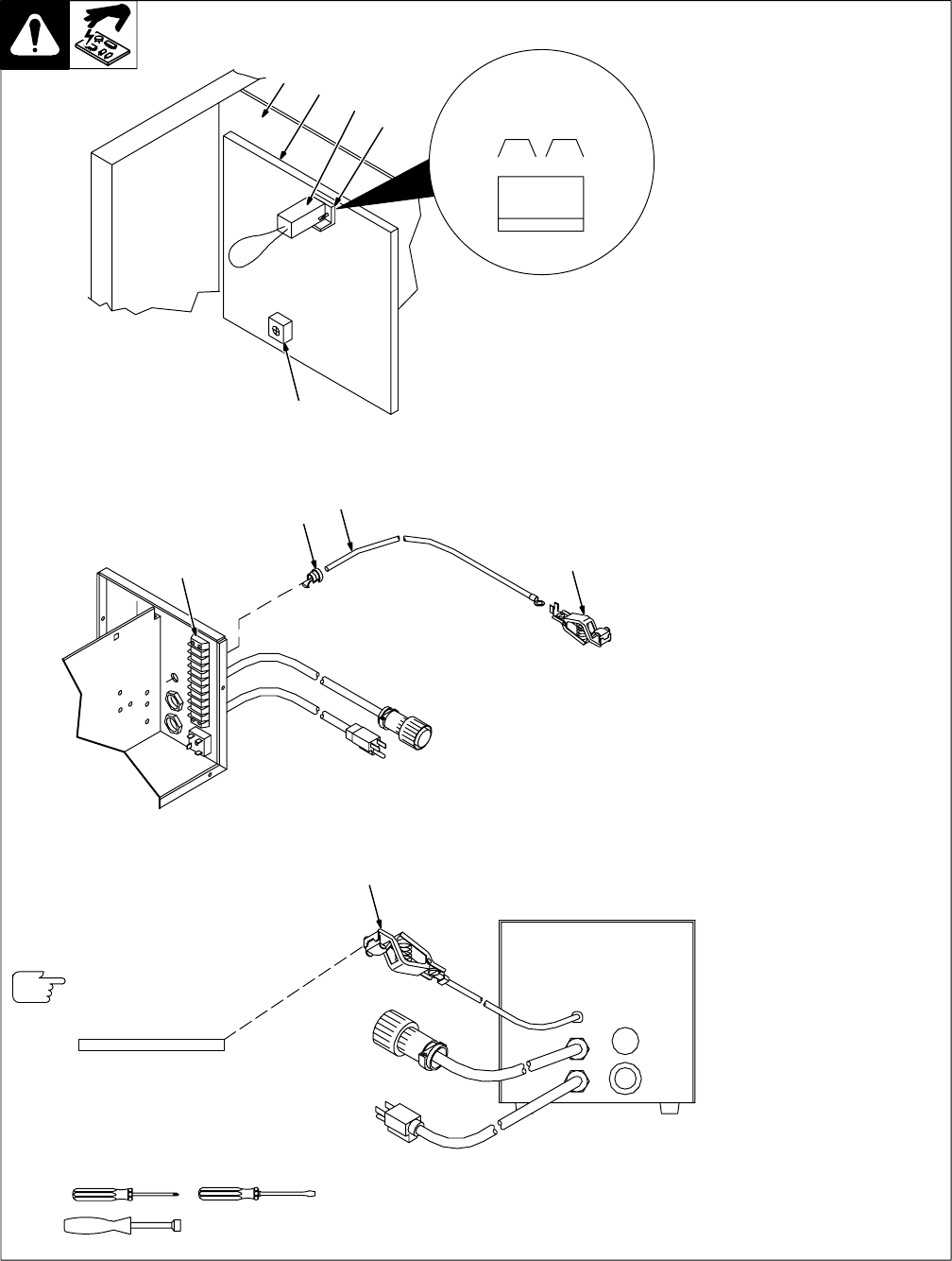
3-5. Installing Voltage Sensing Lead And Motor Start Control Adjustment
150 035-B / Ref. 143 328-K / 149 920-B
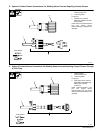
1 Center Baffle
2 Circuit Board PC1
3 Jumper Plug
4 Receptacle RC3
Internal (INT) and external (EXT)
are stamped on PC1 just above
RC3. Unit is shipped with jumper
plug in internal (INT) position.
To install voltage sensing lead,
proceed as follows:
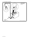
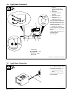
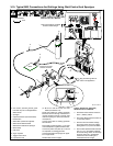
5 Clamp
6 Cord
Connect ring terminal on end of
cord using screw in clamp. Crimp
clamp tabs around cord.
7 Strain Relief
Slide strain relief onto cord
approximately 6 in (152 mm) from
cord end.
Remove upper hole plug from rear
panel.
Insert cord into opening in rear
panel, and secure strain relief into
opening.
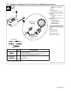
8 Terminal Strip 1T
Connect voltage sensing lead to
terminal strip 1TK at lead 42.
9 Voltage Sensing Lead
For constant current welding
(CC), place jumper plug in the
EXT position. Connect voltage
sensing lead to workpiece.
For constant voltage welding (CV),
place jumper plug in the INT
position. Do not install voltage
sensing lead.
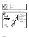
10 Potentiometer R70
To adjust motor ramp speed,
remove protective cap (if present),
and adjust potentiometer R70 using
a small nonconductive screwdriver.
Rotating R70 clockwise increases
the time it takes the motor to ramp
up to speed.
Reinstall wrapper.
Tools Needed:
1/4 in
Front
1
2
3
4
10
123
INT. EXT.
RC3
CV CC
9
Rear View
For CC operation, connect
voltage sensing lead to
workpiece.
Work
. Contactor cord only
on standard model.
5
6
7
8