


OM-877 Page 8
Table 4-1. Cord Size By Ampacity Rating
Cord Size–AWG* Ampacity Of Cord
18 10
14 18
12 25
10 30
8 40
6 50
4 70
2 95
*Cord sizes are based on National Electrical Code (1984 Edition)
specifications for allowable ampacity for not more than two ther-
moset or thermoplastic insulated current-carrying copper conduc-
tors in a cord (see Article 400 in NEC for specific information.)
B. Cord Connections
Using proper cords of desired length, make connections
to the load bank as follows:
1. Remove front access panel from unit (see Figure
5-1).
2. Strip cord jacket back approximately 5 in (127
mm) and separate conductors; strip 1/4 in (6 mm)
of insulation from end of each conductor.
3. Obtain ring terminals of proper capacity and size
to fit 1/4 in (6 mm) terminal studs. Install terminals
securely onto stripped ends of conductors for
both cords.
4. Insert cords up through strain reliefs in bottom of
front access opening. Be sure cords are in cor-
rect locations for 120 volt and 240 volt connec-
tions (see unit nameplate and Figure 4-1).
IMPORTANT: Do not remove existing leads from ter-
minal studs.
5. Remove only the outside nut from each terminal
board stud for 120 and 240 volt connections. Re-
move top nut from ground terminal stud (see
Figure 4-1).
6. Install conductor ring terminals onto studs as in-
dicated in Figure 4-1, and secure with nuts re-
moved in Step 5.
7. Secure cords by tightening strain relief clamp
screws.
8. Reinstall front access panel onto unit.
9. Obtain and install a proper plug that matches the
power source receptacle onto remaining end of
cords.
10. Place cords in storage area while unit is not in
use.
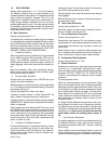
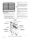
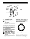
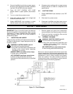
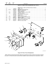
ST-108 013-A
Cord Storage
Area
Ground Terminal – Connect
Ground Conductors
Strain Relief Opening – Insert
120V Cord Up From
Cord Storage Area
Front Access
Panel Removed
120V Terminal L1 – Connect
White Conductor
Front Control Panel
120V Terminal L2 –
Connect Black
Conductor
Input Terminal Board
240V Terminal L2 –
Connect Black Conductor
240V Terminal L1 –
Connect White Conductor
Strain Relief Opening – Insert
240V Cord Up From
Cord Storage Area
Figure 4-1. Input Terminal Board And Ground Connectors