


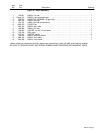

OM-877 Page 9
SECTION 5 – OPERATOR CONTROLS
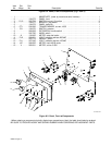
ST-108 014-A
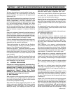
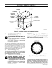
Cord Storage
Area
Amperage Load
Switches
Load Selector
Switch
120/240VAC
Pilot Light For
120VAC Load
AC Voltmeter
Hertz Meter
Front Access Panel
Pilot Light For
240VAC Load
Dual Scale
AC Ammeter
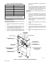
Figure 5-1. Front Panel Controls And Component Locations
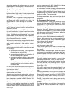
5-1. 120 VOLT LOAD/240 VOLT LOAD
SELECTOR SWITCH (Figure 5-1)
CAUTION: ARCING can damage switch con-
tacts.
• Do not change the position of the selector
switch under load.
Arcing causes the contacts to become pitted
and eventually inoperative.
The 120 VOLT LOAD/240 VOLT LOAD selector switch
is used to select the proper voltage load terminals inside
the unit, and to disconnect and isolate the other voltage
load terminals. Before making selection with selector
switch, be sure that the AMPERAGE load switches are
placed in the OFF positions (see Section 5-3).
5-2. PILOT LIGHTS (Figure 5-1)
Two pilot lights are provided on the unit. The pilot light for
the corresponding voltage load will illuminate when
input voltage is present at the Load Bank.
5-3. AMPERAGE LOAD SWITCHES (Figure 5-1)
CAUTION: INCORRECT SWITCH POSI-
TIONS can damage internal components.
• When operating on 240 volts, set amperage
switches at same position or within one posi-
tion of another.
A balanced load setting at both amperage load
switches is necessary to prevent resistor
damage inside the unit.
IMPORTANT: Always place both AMPERAGE load
switches in the OFF position before connecting a power
source, when changing the 120 VOLT LOAD/240 VOLT
LOAD selector switch position, and after completing
power source output checking procedures.
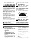
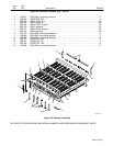
OFF
5
10
15
20
25
30
35
40
45
OFF
5
10
15
20
25
30
35
40
45
+
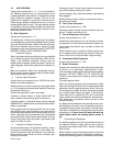
AMPERAGE
Ref. SC-096 625
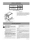
Figure 5-2. Amperage Load Switch Scales
Two AMPERAGE load switches provide the selection of
resistance values when checking output from an ac
power source. The scales around each switch are cali-
brated in amperes with the inside scale for 120 vac input
and the outside scale for 240 vac input (see Figure 5-2).