


OM-1594 Page 19
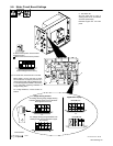
5-8. Meter Circuit Board Settings
Ref. 802 359 / Ref. 186 266
Tools Needed:
1/4 in
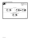
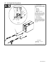
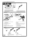
1 Meter Board PC2
2 DIP Switch S2
Set DIP switch S2 for type of
welding power source, and desired
wire feed speed display.
Reinstall hinged door and side
panel.
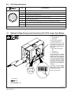
12 345
12345
12345
12345
Or
Or
Meters/Minute
Inches/Minute
Digital Meter Display
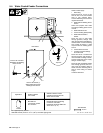
Arc Voltage Sensing Using Voltage Sensing
Lead For Welding Power Source That Does
Not Support Pins F And H
Voltage Sensing Function
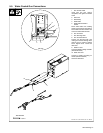
Arc Voltage Sensing Using Feedback From
Welding Power Source That Does Support
Pins F And H
12
X Means switch position does not affect
specified function.
.
Means switch must be in this position.
2
1
. For sense lead, connect PLG51 to PLG50.
Before feeder can be used with a power
source that does not support pins F and H, a
voltage sensing lead must be installed in feed-
er. Volt sensing lead kit 209867. See section
5-7 for information regarding installation of
voltage sensing lead.
For voltage feedback, connect PLG51 to
PLG52.
12345
Switch settings from the factory.