


page 5
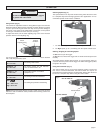
OPERATION
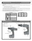
To reduce the risk of injury, wear safety goggles
or glasses with side shields.
WARNING!
Positions 1- 5
10 - 17 in. lbs.
Position 6 - 10
18 - 34 in. lbs.
Position 11 - 15
35 - 50 in. lbs.
Position 16 - 19
51 - 76 in. lbs.
Drill
Low 220 in. lbs.
High 80 in. lbs.
For driving small screws.
For driving screws into soft materials
such as wood veneers, etc.
For terminal screws on electrical
equipment, etc.
For driving screws into hardwood.
For drilling and powerful screwdriving.
The torque specifications shown here are approximate values obtained
with a fully charged battery pack.
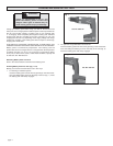
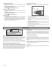
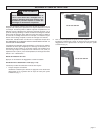
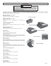
Using Clutch (Fig. 3)
This tool has an adjustable clutch for driving different types of screws into
different materials. When properly adjusted, the clutch will slip at a preset
torque to prevent driving the screw too deep and to prevent damage to
the screw or tool. Refer to the table below to select the correct position
for the type of material and screw size you are using.
To adjust the clutch, turn the clutch adjusting ring to one of the nineteen
positions shown on the adjusting ring.
NOTE: Because the above settings are only a guide, use a piece of scrap
material to test the different clutch positions before driving screws into
the workpiece.
Fig. 3
Clutch
Adjusting Ring
Position
Numbers
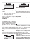
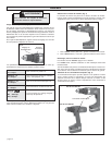
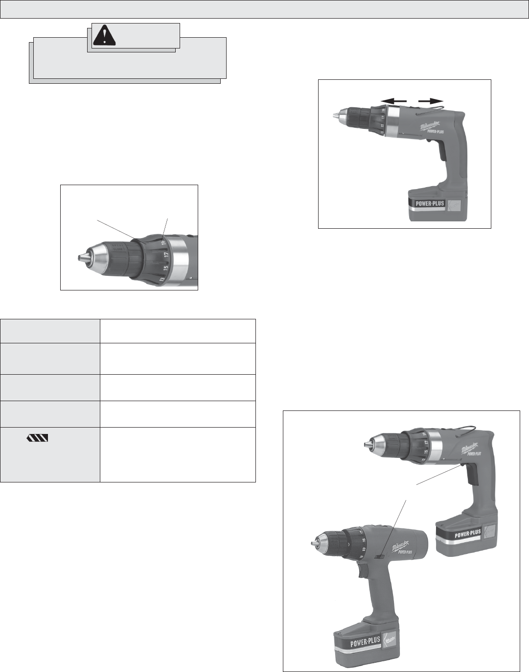
Selecting Speed (Fig. 4)
The speed selector is on top of the motor housing. Allow the tool to come
to a complete stop before changing speeds. See “Applications” for rec-
ommended speeds under various conditions.
Fig. 4
Low
High
1. For Low speed (up to 360 RPM), push the speed selector forward.
2. For High speed (up to 1,100 RPM), push the speed selector back.
Starting, Stopping & Controlling Speed
To start the tool, pull the trigger.
To stop the tool, release the trigger and an electric brake stops the tool
instantly.
All models feature variable speed control. To vary the speed, simply in-
crease or decrease pressure on the trigger. The further the trigger is pulled,
the greater the speed.
Using Control Switch (Fig. 5)
The control switch may be set to three positions: forward, reverse and
lock. Due to a lockout mechanism, the control switch can only be ad-
justed when the ON/OFF switch is not depressed. Always allow the motor
to come to a complete stop before using the control switch.
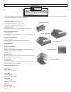
Control Switch
Cat. No. 0501-02
Cat. No. 0502-02
Fig. 5