


4
5
1
2
3
4
6
5
ASSEMBLY
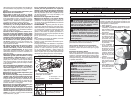
WARNING Recharge only with the char-
ger specifi ed for the battery. For specifi c charg-
ing instructions, read the operator’s manual
supplied with your charger and battery.
SPECIFICATIONS
Cat. No. Volts DC No Load RPM Spindle Thread Size Wheel Size Min. Wheel RPM Rating
0725-20 28 8000 5/8"-11 4-1/2" 8800
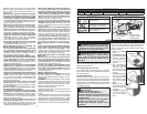
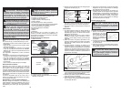
FUNCTIONAL DESCRIPTION
SYMBOLOGY
Direct Current
Underwriters Laboratories, Inc.
United States and Canada
No Load Revolutions per
Minute (RPM)
Kickback is the result of power tool misuse and/or
incorrect operating procedures or conditions and
can be avoided by taking proper precautions as
given below.
• Maintain a fi rm grip on the power tool and posi-
tion your body and arm to allow you to resist
kickback forces. Always use auxiliary handle,
if provided, for maximum control over kickback
or torque reaction during start-up. The operator
can control torque reactions or kickback forces, if
proper precautions are taken.
• Never place your hand near the rotating acces-
sory. Accessory may kick back over your hand.
• Do not position your body in the area where
power tool will move if kickback occurs. Kick-
back will propel the tool in direction opposite to
the wheel’s movement at the point of snagging.
• Use special care when working corners, sharp
edges etc. Avoid bouncing and snagging the
accessory. Corners, sharp edges or bouncing
have a tendency to snag the rotating accessory
and cause loss of control or kickback.
• Do not attach a saw chain woodcarving blade
or toothed saw blade. Such blades create fre-
quent kickback and loss of control.
Safety Warnings Specific for Grinding and
Abrasive Cutting-Off Operations:
• Use only wheel types that are recommended
for your power tool and the specifi c guard
designed for the selected wheel. Wheels for
which the power tool was not designed can not
be adequately guarded and are unsafe.
• The guard must be securely attached to the
power tool and positioned for maximum safety,
so the least amount of wheel is exposed to-
wards the operator. The guard helps to protect
operator from broken wheel fragments and ac-
cidental contact with wheel.
• Wheels must be used only for recommended
applications. For example: do not grind with the
side of cut-off wheel. Abrasive cut-off wheels are
intended for peripheral grinding, side forces applied
to these wheels may cause them to shatter.
• Always use undamaged wheel fl anges that are
of correct size and shape for your selected
wheel. Proper wheel fl anges support the wheel
thus reducing the possibility of wheel breakage.
Flanges for cut-off wheels may be different from
grinding wheel fl anges.
• Do not use worn down wheels from larger
power tools. Wheel intended for larger power tool
is not suitable for the higher speed of a smaller
tool and may burst.
Additional Safety Warnings Specifi c for Abra-
sive Cutting-Off Operations:
• Do not jam the cut-off wheel or apply excessive
pressure. Do not attempt to make an excessive
depth of cut. Overstressing the wheel increases
the loading and susceptibility to twisting or bind-
ing of the wheel in the cut and the possibility of
kickback or wheel breakage.
• Do not position your body in line with and
behind the rotating wheel. When the wheel, at
the point of operation, is moving away from your
body, the possible kickback may propel the spin-
ning wheel and the power tool directly at you.
• When wheel is binding or when interrupting a
cut for any reason, switch off the power tool
and hold the power tool motionless until the
wheel comes to a complete stop. Never attempt
to remove the cut-off wheel from the cut while
the wheel is in motion otherwise kickback may
occur. Investigate and take corrective action to
eliminate the cause of wheel binding.
• Do not restart the cutting operation in the
workpiece. Let the wheel reach full speed and
carefully reenter the cut. The wheel may bind,
walk up or kickback if the power tool is restarted
in the workpiece.
• Support panels or any oversized workpiece to
minimize the risk of wheel pinching and kick-
back. Large workpieces tend to sag under their
own weight. Supports must be placed under the
workpiece near the line of cut and near the edge
of the workpiece on both sides of the wheel.
• Use extra caution when making a "pocketcut"
into existing walls or other blind areas. The
protruding wheel may cut gas or water pipes, elec-
trical wiring or objects that can cause kickback.
Safety Warnings Specifi c for Sanding Opera-
tions:
• Do not use excessively oversized sanding disc
paper. Follow manufacturers recommenda-
tions, when selecting sanding paper. Larger
sanding paper extending beyond the sanding
pad presents a laceration hazard and may cause
snagging, tearing of the disc or kickback.
Safety Warnings Specifi c for Wire Brushing
Operations:
• Be aware that wire bristles are thrown by the
brush even during ordinary operation. Do not
over stress the wires by applying excessive
load to the brush. The wire bristles can easily
penetrate light clothing and/or skin.
• If the use of a guard is recommended for wire
brushing, do not allow any interference of the
wire wheel or brush with the guard. Wire wheel
or brush may expand in diameter due to workload
and centrifugal forces.
Additional Safety Warnings
• Maintain labels and nameplates. These carry
important information. If unreadable or missing,
contact a MILWAUKEE service facility for a free
replacement.
• WARNING: Some dust created by power sanding,
sawing, grinding, drilling, and other construction
activities contains chemicals known to cause
cancer, birth defects or other reproductive harm.
Some examples of these chemicals are:
• lead from lead-based paint
• crystalline silica from bricks and cement and other
masonry products, and
• arsenic and chromium from chemically-treated
lumber.
Your risk from these exposures varies, depending
on how often you do this type of work. To reduce
your exposure to these chemicals: work in a well
ventilated area, and work with approved safety
equipment, such as those dust masks that are spe-
cially designed to fi lter out microscopic particles.
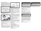
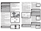
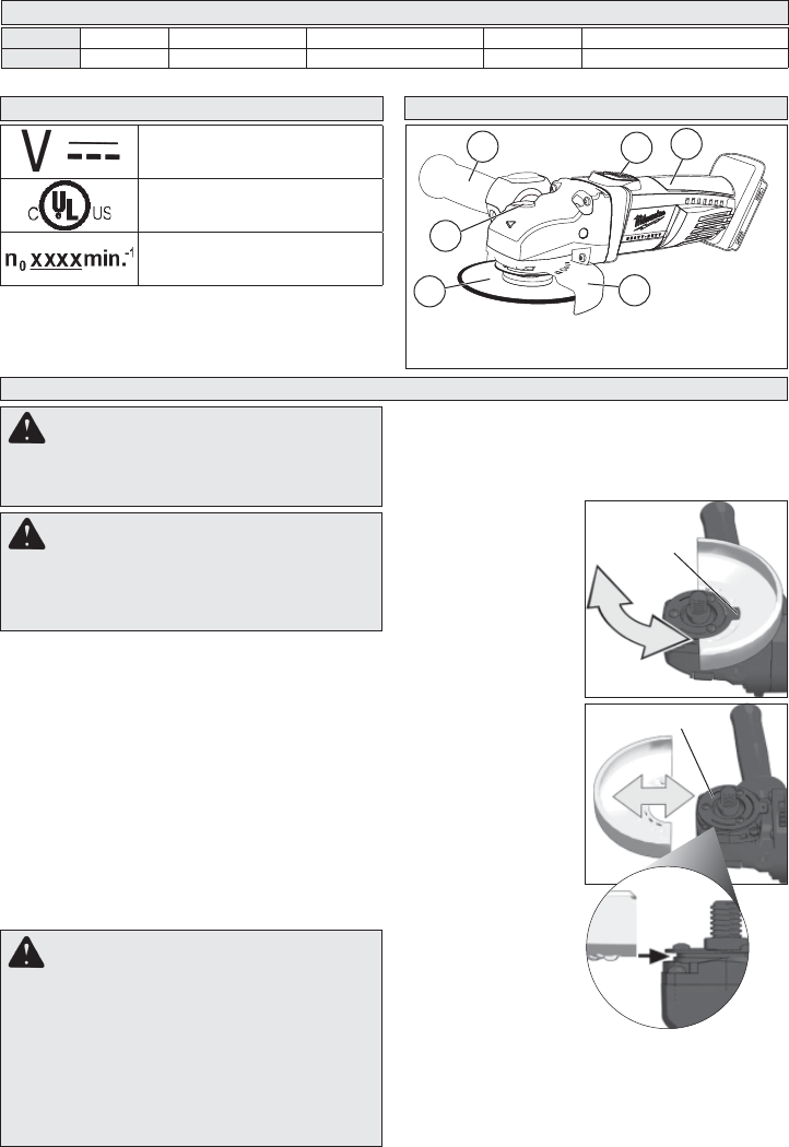
1. Spindle lock
2. On/off switch
3. Handle
4. Side handle
5. Type 27 guard
6. Grinding disc
Removing Battery Pack from Tool
Push in the release buttons and pull the battery
pack away from the tool.
Inserting Battery Pack into Tool
To insert the battery pack onto the tool, slide the
pack onto the body of the tool. Make sure it latches
securely into place.
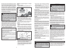
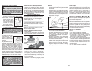
Installing Side Handle
The side handle may be installed on either side of
gear case for right or left handed use. Position side
handle in the location which offers best control and
guard protection. To install, thread side handle into
side handle socket on desired side of gear case
and tighten securely.
WARNING Always remove battery
pack before changing or removing acces-
sories. Only use accessories specifically
recommended for this tool. Others may be
hazardous.
WARNING To reduce the risk of injury
when grinding:
• ALWAYS use the proper guard.
• ALWAYS properly install the guard.
• ALWAYS hold the tool fi rmly with both hands
using the handles provided before and
during grinding.
• NEVER use a wheel that has been dropped.
• NEVER bang grinding disc onto work.
• NEVER grind without proper safety
equipment.
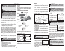
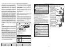
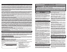
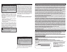
Installing, Removing and Adjusting the Guard
This tool is shipped with the guard installed. The
guard must be used when using the tool as a
grinder. The guard may be removed when using
tool as a sander.
1. Remove the battery
pack.
2. To remove the guard,
place the tool upside
down on a level sur-
face. Remove any
accessories from
spindle.
3. Use a screwdriver to
lift up the retaining
tab and rotate the
guard to the front of
the tool. Pull off the
guard.
4. To install the guard,
line up the guard
from the front of the
tool. Slide the guard
under the spindle
plate.
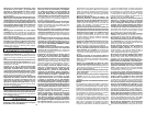
5. Rotate the guard to
the position to best
protect the operator
(Fig. 2).
6. To adjust the guard,
rotate the guard to
one of the detent
slots.
Spindle plate
Retaining
tab
Use only MILWAUKEE M28™ or V28
®
battery packs.