


4
5
ASSEMBLY
WARNING Recharge only with the char-
ger specifi ed for the battery. For specifi c charg-
ing instructions, read the operator’s manual
supplied with your charger and battery.
FUNCTIONAL DESCRIPTION
SYMBOLOGY
Direct Current
Underwriters Laboratories, Inc.
United States and Canada
No Load Revolutions per
Minute (RPM)
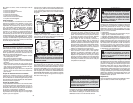
SPECIFICATIONS
Cat. No. Volts DC No Load RPM Blade Size Arbor Depth of Cut At 90°
0740-20 28 3 200 6-7/8" 20 mm 0 to 2-3/8"
• Lower guard should be retracted manually
only for special cuts such as "Plunge Cuts"
and "Compound Cuts". Raise lower guard by
retracting handle and as soon as blade enters
the material, the lower guard must be released.
For all other sawing, the lower guard should oper-
ate automatically.
• Always observe that the lower guard is cov-
ering the blade before placing saw down on
bench or fl oor. An unprotected, coasting blade will
cause the saw to walk backwards, cutting whatever
is in its path. Be aware of the time it takes for the
blade to stop after switch is released.
• Maintain labels and nameplates. These carry
important information. If unreadable or missing,
contact a MILWAUKEE service facility for a free
replacement.
• WARNING: Some dust created by power sanding,
sawing, grinding, drilling, and other construction
activities contains chemicals known to cause
cancer, birth defects or other reproductive harm.
Some examples of these chemicals are:
• lead from lead-based paint
• crystalline silica from bricks and cement and other
masonry products, and
• arsenic and chromium from chemically-treated
lumber.
Your risk from these exposures varies, depending
on how often you do this type of work. To reduce
your exposure to these chemicals: work in a well
ventilated area, and work with approved safety
equipment, such as those dust masks that are spe-
cially designed to fi lter out microscopic particles.
• Do not touch material after it has been cut. Cut
material may be very hot.
• Do not use cutting oil. The use of cutting oil may
cause a fi re.
• Do not use tool near flammable material.
Sparks may cause fi re.
• Do not cut workpieces covered or stained
with gas, oil, solvents, thinners, etc. Exposure
to these materials may damage the transparent
guard.
• Do not remove the transparent front guard. If
the transparent front guard is damaged or miss-
ing, return tool to authorized service station for
replacement.
• Do not start the blade when in contact with
workpiece. Wait for blade to reach full speed
before beginning cut.
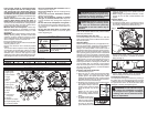
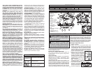
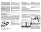
1. Front handle
2. Upper guard
3. Lock-off button
4. Trigger
5. Handle
6. Shoe
7. Lower guard lever
8. Lower guard
9. Blade bolt
10. Blade fl ange
11. Blade
12. LED
13. Transparent
front guard
14. Wrench
15. Spindle lock button
16. Depth adjusting lever
17. Overload protector
Removing Battery Pack from Tool
Push in the release buttons and pull the battery
pack away from the tool.
Inserting Battery Pack into Tool
To insert the battery pack onto the tool, slide the
pack onto the body of the tool. Make sure it latches
securely into place.
Selecting Blade
Select a blade appropriate for your application. Re-
fer to the “Accessories” section for a list of blades to
be used for the proper applications of this tool.
Always use sharp blades. Dull blades tend to
overload the tool and increase the chance of KICK-
BACK. Only use thin kerf blades with a maximum
safe operating speed greater than the no load RPM
marked on the tool's nameplate. Read the blade
manufacturer's instructions before use. Do not use
any type of abrasive cut-off wheel or dry diamond
cutting blades. Use the correct blade type for your
application. Using the wrong blade may result in
reduced performance or damage to the blade. Do
not use blades that are cracked or have broken
teeth. Do not sharpen ferrous metal cutting blades;
see the blade manufacturer's recommendations
regarding sharpening.
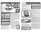
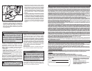
Installing and Removing Blades
1. Remove battery pack.
2. Place the saw on a fl at surface with the blade
facing upwards. To remove the bolt from the
spindle, push in the spindle lock button. While
holding in the spindle lock button, use the wrench
provided with the tool to turn the bolt clockwise.
Remove the bolt and blade fl ange.
3. Slide the lower guard lever up to raise the lower
guard. Remove the blade from
the spindle. Always clean the
spindle, upper guard and lower
guard to remove any dirt and
dust.
NOTE: Do not remove inner
blade fl ange. Larger diameter
of inner fl ange should face the
blade.
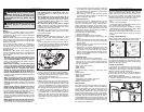
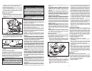
4. To install a blade, place
the blade on the spindle
with the teeth pointing
in the same direction as
the arrow on the lower
guard. Release the lower guard lever.
WARNING Always remove battery
pack before changing or removing acces-
sories. Only use accessories specifically
recommended for this tool. Others may be
hazardous.
4. Lift the depth adjusting lever up towards the
motor housing to secure the shoe position.
Transparent Front Guard
The transparent front guard allows easy viewing of
the cutting line. If the transparent guard is cracked
or broken, return it to a MILWAUKEE service facility
for replacement. Never use the metal cutter with a
damaged or missing transparent guard.
3. Raise or lower the shoe to the desired position.
For the proper depth setting, the blade should
extend no more than 1/4" below the material
being cut (Fig. 2).
5. Place the blade fl ange on the spindle and hand
tighten the bolt.
6. While holding in the spindle lock button, use the
wrench to turn the bolt counterclockwise and
tighten.
Adjusting Depth
1. Remove battery pack.
2. To adjust the depth of the cut, hold the saw by
the handle and loosen the depth adjusting lever
by pushing it down toward the shoe (Fig. 1).
1/4"
Fig. 1
Fig. 2
WARNING To reduce the risk of injury,
do not remove the transparent front guard.
If the transparent front guard is damaged
or missing, return tool to authorized service
station for replacement.
1
2
3
5
4
6
7
8
9
10
11
15
16
14
13
17
12
Arrow
Bolt
Outer
fl ange
Inner
fl ange
Spindle
Use only MILWAUKEE M28™ or V28
®
battery packs.