


6 7
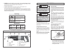
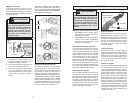
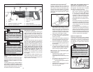
2. Release collar and the spring loaded
mechanism will clamp the blade fi rmly
in place.
3. Twist collar in the opposite direction of
the arrow to ensure that the blade is
locked into the clamp.
4. Tug on blade to make sure it is securely
locked in place.
5. To remove a blade, twist collar in the
direction of the arrow while pulling on
the blade. Be careful when handling hot
blades.
Quik-Lok
®
Blade Clamp Maintenance
• Periodically clean dust and debris from
the Quik-Lok
®
Blade Clamp with dry
compressed air.
• If the collar resists twisting, twist the
collar back and forth to shake debris
loose.
• Periodically lubricate Quik-Lok
®
Blade
Clamp with a dry lubricant such as
graphite.
Removing broken blades from the Quik-
Lok
®
Blade Clamp
• Remove battery pack before removing
blades.
• Broken blades can be removed by the
following methods.
• Point the tool downward, twist the collar,
and shake the tool up and down (DO
NOT turn the tool on while your fi ngers
are holding the blade clamp open). The
shank of the broken blade should drop
out of the clamp.
• If shaking the tool doesn't work...
In most cases, a corner of the broken
blade will extend beyond the blade
clamp. Simply twist the collar and pull
the broken blade out of the clamp by this
corner.
• If the broken stub doesn't extend far
enough to be grabbed by its corner, use
a thin blade with small teeth (such as a
metal cutting blade) to hook the blade
that is jammed in the clamp while twist-
ing the collar and pull it out.
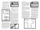
Adjusting the Pivot Shoe
The shoe can be adjusted forward or back-
ward to six positions to take advantage of the
unused portion of the blade or for special jobs
requiring low blade clearance.
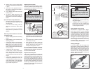
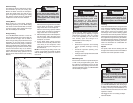
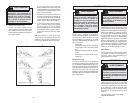
WARNING
To reduce the risk of injury, be sure
the blade always extends beyond
the shoe and work throughout the
stroke. Blades may shatter if they
impact the work or shoe (Fig. 2).
Fig. 2
1/4 Turn
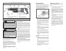
1. To adjust the shoe, pull the shoe release
lever down 1/4 turn and slide the shoe
forward or backward to the desired posi-
tion.
2. To lock the shoe in position, push the
shoe release lever up.
3. After adjusting the shoe, slowly pull
the trigger to be sure the blade always
extends beyond the shoe and your
workpiece throughout the stroke.
DO NOT OPERATE SAWZALL WITHOUT
SHOE. STRIKING THE SPINDLE AGAINST
WORKPIECE MAY DAMAGE THE RECIP-
ROCATING MECHANISM.
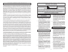
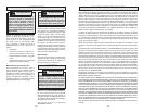
Impact Protection System
This model is equipped with a unique pat-
ented gearing system that provides effi cient
power transmission and extended life in the
most diffi cult cutting applications. This du-
rable system will absorb impacts, blade lock
ups, and motor stalls. This model can be used
for extreme cutting applications such as large
diameter pipe, thick metal, pallets, and heavy
demolition and renovation work as well as for
general purpose cutting.
Fig. 3
Stroke
OPERATION
Starting, Stopping and Controlling Speed
1. To start the tool, grasp the handle fi rmly
and pull the trigger.
2. To stop the tool, release the trigger. Al-
low the tool to come to a complete stop
before removing the blade from a partial
cut or laying the tool down.
WARNING
To reduce the risk of injury, keep
hands away from the blade and
other moving parts. Always wear
safety goggles or glasses with side
shields.
Trigger Speed Control Switch
The Sawzall
TM
is equipped with a trigger
speed control switch. It may be operated
at any speed from zero strokes per minute
to full speed. Always start tool before blade
contacts the workpiece. To vary the speed,
simply increase or decrease the pressure on
the trigger. The further the trigger is pulled,
the greater the speed. To stop the tool, re-
lease the trigger and allow the tool to stop
completely before removing from a partial
cut or before laying the tool down.
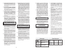
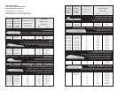
Locking the Trigger
To lock the trigger, slide the trigger lock
switch until the "locked" symbol is visible. The
trigger will not work while the switch is in the
locked position. Always lock the trigger and
remove the battery pack before performing
maintenance and changing accessories.
Lock the trigger when storing the tool and
when the tool is not in use.
Trigger Lock
Switch
Symbols
Unlocked
Locked
Fig. 4