


4
5
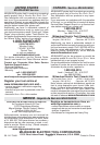
Fig. B
Fig. C
Fig. A
GROUNDING
WARNING Improperly connecting the
grounding wire can result in the risk of elec-
tric shock. Check with a qualifi ed electrician
if you are in doubt as to whether the outlet is
properly grounded. Do not modify the plug
provided with the tool. Never remove the
grounding prong from the plug. Do not use
the tool if the cord or plug is damaged. If
damaged, have it repaired by a MILWAUKEE
service facility before use. If the plug will not
fi t the outlet, have a proper outlet installed by
a qualifi ed electrician.
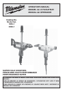
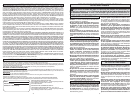
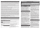
Grounded Tools: Tools with Three Prong Plugs
Tools marked “Grounding Required” have a three
wire cord and three prong grounding plug. The
plug must be connected to a properly grounded
outlet (See Figure A). If the tool should electrically
malfunction or break down, grounding provides a
low resistance path to carry electricity away from
the user, reducing the risk of electric shock.
The grounding prong in the plug is connected
through the green wire inside the cord to the
grounding system in the tool. The green wire in the
cord must be the only wire connected to the tool's
grounding system and must never be attached to
an electrically “live” terminal.
Your tool must be plugged into
an appropriate outlet, properly
installed and grounded in accord-
ance with all codes and ordinances.
The plug and outlet should look like
those in Figure A.
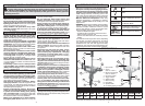
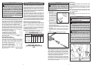
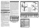
Double Insulated Tools:
Tools with Two Prong Plugs
Tools marked “Double Insulated” do not require
grounding. They have a special double insula-
tion system which satisfi es OSHA requirements
and complies with the applicable standards of
Underwriters Laboratories, Inc.,
the Canadian Standard Asso-
ciation and the National Elec-
trical Code. Double Insulated
tools may be used in either of
the 120 volt outlets shown in
Figures B and C.
Grounded tools require a three wire extension
cord. Double insulated tools can use either a two
or three wire extension cord. As the distance from
the supply outlet increases, you must use a heavier
gauge extension cord. Using extension cords with
inadequately sized wire causes a serious drop in
voltage, resulting in loss of power and possible tool
damage. Refer to the table shown to determine the
required minimum wire size.
The smaller the gauge number of the wire, the
greater the capacity of the cord. For example, a 14
gauge cord can carry a higher current than a 16
gauge cord. When using more than one extension
cord to make up the total length, be sure each cord
contains at least the minimum wire size required.
If you are using one extension cord for more than
one tool, add the nameplate amperes and use the
sum to determine the required minimum wire size.
Guidelines for Using Extension Cords
• If you are using an extension cord outdoors, be
sure it is marked with the suffi x “W-A” (“W” in
Canada) to indicate that it is acceptable for outdoor
use.
• Be sure your extension cord is properly wired
and in good electrical condition. Always replace a
damaged extension cord or have it repaired by a
qualifi ed person before using it.
• Protect your extension cords from sharp objects,
excessive heat and damp or wet areas.
READ AND SAVE ALL
INSTRUCTIONS FOR FUTURE
USE.
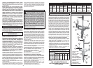
Recommended Minimum Wire Gauge
for Extension Cords*
Extension Cord Length
* Based on limiting the line voltage drop to fi ve volts
at 150% of the rated amperes.
Nameplate
Amperes
0 - 2.0
2.1 - 3.4
3.5 - 5.0
5.1 - 7.0
7.1 - 12.0
12.1 - 16.0
16.1 - 20.0
25'
18
18
18
18
16
14
12
75'
18
18
16
14
12
10
100'
18
16
14
12
10
150'
16
14
12
12
50'
18
18
18
16
14
12
10
EXTENSION CORDS
ASSEMBLY
WARNING To reduce the risk of injury,
always unplug tool before changing or re-
moving accessories. Only use accessories
specifi cally recommended for this tool. Others
may be hazardous.
Installing Bits into Morse Taper Sockets
A No. 3 Morse Taper Socket is furnished as stan-
dard equipment on Super Hole-Shooter Cat. No.
2404-1. Before inserting the drill bit, be sure its
taper matches the socket taper. To insert drill bit,
push the shank of the bit fi rmly into the socket. This
is all that is necessary to properly seat the bit for
drilling. Always keep the taper shanks clean, free
of nicks and coated with a fi lm of oil.
To remove the bit from the socket, unscrew the
knurled taper socket cap and pull out the bit and
the socket. Once removed, the bit can be gently
knocked free with a soft metal mallet. Replace the
socket and the knurled cap.
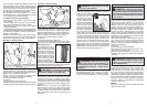
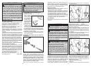
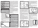
Installing Bits into Keyed Chucks
1. Unplug tool.
2. Open the chuck
jaws wide enough
to insert the bit. Be
sure the bit shank
and chuck jaws
are clean. Dirt par-
ticles may prevent
the bit from lining
up properly.
3. Insert the bit into
the chuck. Center
the bit in the chuck jaws and lift it about 1/16"
off of the bottom. Then, tighten the chuck jaws
by hand to align the bit.
4. Place the chuck key in each of the three holes in
the chuck, turning it clockwise as shown. Tighten
securely.
5. To remove the bit, insert the chuck key into one
of the holes in the chuck and turn it counterclock-
wise.
Fig. 2
Fig. 1
Bit Selection
• Use sharp bits. Sharp bits are less likely to bind
when drilling.
• Use the proper bit for the job. There are many
types of bits designed for specifi c purposes. Check
the information on the bit's packaging for proper
usage.
• Do not use bits larger than the rated capacity of the
drill. Gear damage or motor overload may result
(see "Specifi cations").
Pipe Handle
Thread pipe handle into the threaded hole in the
motor housing.
Bit binding
OPERATION
WARNING
To reduce the risk of per-
sonal injury when drilling, always hold tool by
the insulated gripping surfaces when perform-
ing an operation where the cutting tool may
contact hidden wiring or its own cord. Contact
with a "live" wire will make exposed metal
parts of the tool "live" and shock the operator.
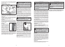
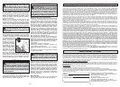
WARNING
When drilling, always brace
the drill against a solid fi xed object (such as
a stud) in preparation for a sudden reaction.
When drilling, never use your body to brace
drill.
Never put your hands (or other body parts)
between the part of the drill being braced and
the object it is being braced against. Hands
(or other body parts) that are in the path of the
reaction can be pinched, crushed or broken.
B
A
Fig. 3
WARNING To reduce the risk of injury,
always wear eye protection.