


6
7
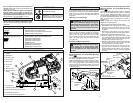
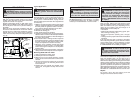
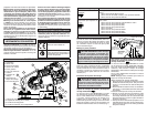
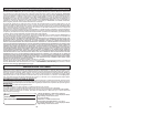
Attaching the Band Saw
1. Use the hex wrench pro-
vided to remove the front
handle retaining screw
and handle (Fig. 4). Store
the handle for future use.
2. Pull out the locking pin
and swing the mounting
bracket forward (Fig. 5).
Mounting
Bracket
Band Saw
Blade
Clearance
Slot
Locking
Pin
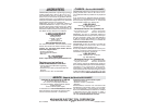
Dampening Screw
The dampening screw is intended to prevent vibra-
tion while the tool is in operation.
• On older models of band saws, overtightening the
dampening screw will reduce blade tension, which
may cause the blade to slip.
• Overtightening the dampening screw will bend
the pully guard and potentially cause excessive
wear on the blade.
• Excessive vibration may occur if the blade is worn
and needs replacing.
1. Unplug tool/remove battery pack.
2. With the tool properly mounted, adjust the damp-
ening screw so that it contacts the front pulley
guard (Fig. 6).
3. Tighten the locking nut after adjusting the damp-
ening screw.
4. If clearance exists or the tool does not cut
smoothly when in operation, loosen the lock-
ing nut, insert a hex wrench and tighten screw
securely against the front pulley guard.
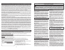
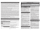
ADJUSTMENTS
WARNING To reduce the risk of injury,
always un plug tool or remove battery pack
before making any adjustments.
Front Pulley
Guard Skirt
Locking Nut
Dampening
Screw
Fig. 5
Fig. 6
Fig. 3
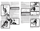
3. Ensure the tool us unplugged or the battery pack
is removed.
4. With the tool equipped with a blade, place the
tool on the table with the blade resting in the
clearance slot in the work surface. Support it
by the handle.
5. Line up the front handle and mounting slot with
the key in the mounting bracket.
6. Install the front handle screw and tighten se-
curely.
Hex
Wrench
Front
Handle
Fig. 4
Retaining
Screw
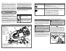
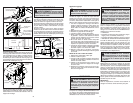
Deep Cut
Regular Cut
3/8"
Washer
3/8"-16 x 1"
Socket Head
Screw
28-10-0325
Mounting Bracket
Mounting
Block
Clamp
Mounting
Block
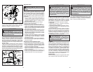
Installing the 28-10-0325 Mounting Bracket
6. With the locking pin secured into the mount-
ing block clamp, line up the holes in the
28-10-0325 mounting bracket with the holes in
the 42-28-0250 mounting block (for deep cut or
regular cut), and secure in place with the wash-
ers and socket head screws, as shown (Fig. 3).
Band Saw Blade
Work Surface
Mounting Block
Clamp Nut
Support Pad
(Deep Cut)
Work Piece
Stop
Work
Surface
Band
Saw Blade
Mounting
Vise
Chain Hook
Mounting
Vise
Swivel
Pin
Crank Nut
Support Pad
(Regular Cut)
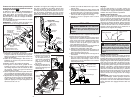
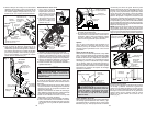
Adjustments
Once the tool is mounted on the table, check for
proper positioning of the tool and blade relative
to the table. Two simple adjustments will provide
straight, parallel cuts.
Vertical Blade Adjustment
When properly adjusted, the blade should be at
a 90
o
angle with the work surface (Fig. 5). Insert
the hex wrench into the head of the front handle
retaining screw. Place a square on the work support
surface and against the side of the blade, above the
teeth. Grasp the switch handle and rotate the tool
until the side of the blade is fl ush with the vertical
side of the square. Securely tighten the upper and
lower mounting bracket screws.
Parallel Blade Adjustment
Loosen the two mounting block clamp nuts ap-
proximately three turns and tap the ends of the bolts
to free them (Fig. 6a). This will provide maximum
movement for adjusting purposes. Line up the back
of the tool’s workpiece stop with the edge of the
support pad (Fig. 6b). This will provide clearance
between the work piece stop and large work pieces
when the tool is raised to the “locked” position.
Place the square against the vertical supports of
the mounting vice and the side of the blade, above
the teeth (Fig. 7). Grasp the handle and pivot the
tool until the side of the blade is fl ush with the
square. Securely tighten the mounting block clamp
nuts (Fig. 6a).
NOTE: After following the complete assembly
instructions, make a few trial cuts to be sure the
blade is square with the stock. With the tool un-
plugged/battery removed, make minor adjustments
as necessary.
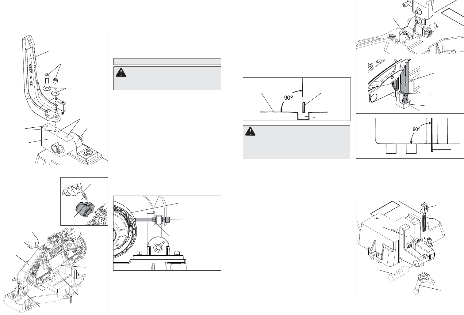
Vice Assembly
Insert the swivel pin into the hole in the mounting
vise and center it. Position the chain hook with the
fi ngers facing the table and insert into the recessed
hole in the swivel pin. Thread the crank nut onto
the chain hook until the threads are at least even
with the bottom of the crank nut (Fig. 8).
For corded Band Saws: After the table is com-
pletely assembled and adjusted, place the power
cord over the top of the tool and secure it to the
mounting bracket.
Fig. 6b
Fig. 6a
Fig. 5
Fig. 7
Fig. 8
Clearance Slot
WARNING On band saws with adjust-
able work piece stops, extend the work piece
to its longest position before setting the
support pad. Otherwise, the saw blade could
strike the band saw table.