


page 6
OPERATION
These rotary hammers have an Electronic Feedback Control Circuit (EFCC)
which helps improve the operation and life of the tool.
Soft Start
The Soft-Start feature reduces the amount of torque reaction to the tool and
the user. This feature gradually increases the motor speed up from zero to
the speed set by the speed control dial.
Feedback Control
The electronic speed control system allows the tool to maintain constant
speed between no-load and load conditions.
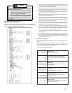
Service Indicator Light
These hammers feature a service indicator light. When the red service light
turns on, the tool is ready for servicing. Return the tool to an authorized
service center.
NOTE: When the service light is on, the tool will continue to run for a few
hours and then the motor will shut off.
Power Indicator Light
When the green power indicator light is on, current is entering the Elec-tronic
Feedback Control Circuit (EFCC) and the tool is ready for operation.
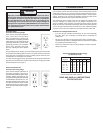
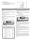
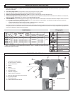
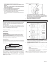
Selecting Action (Fig. 6)
(Cat. No. 5315-21 & 5321-21)
The 5315-21 and 5321-21 Rotary Hammers feature a stop rotation knob.
The stop rotation knob may be set for either “hammering-only” or “ham-
mering-with-rotation”. The 5315-21 Rotary Hammer has a third setting that
allows the angle of the chisel blade to be adjusted.
To reduce the risk of injury, when using chis-
els or (other hammering-only accessories) in
the 5315-21 Rotary Hammer, set the tool in the
“hammering-only” position.
1. Hammering only. For use with “hammering-only” accessories. Use
this setting (1) for chiseling or setting self-drilling anchors.
2. Hammering with rotation. Use this setting (2) for drilling holes with
drill bits.
3. Chisel adjustment. (Cat. No. 5315-21 only) Use this setting (3) to
adjust the angle of the chisel blade in relation to the tool. With a chisel
mounted in the tool:
• turn the knob to this setting
• twist the chisel to the desired angle
• set the tool for hammering only
NOTE: To engage the hammering mechanism, maintain pressure on the bit.
When the pressure on the bit is released, the hammering will stop.
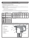
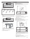
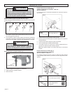
Setting the Depth Gauge (Fig. 5)
1. Loosen the depth gauge adjustment knob (2).
2. Slide the depth gauge rod (1) backward or forward until it is set for the
desired depth. The drilling depth is the distance between the tip of the
bit and the tip of the depth gauge rod.
3. Tighten the depth gauge adjustment knob securely.
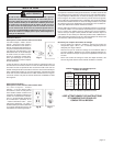
WARNING
To reduce the risk of injury, wear safety goggles or
glasses with side shields.
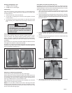
Hammering Only
SDS Max Drive System (Cat. No. 5315-21)
When using chisels (or other “hammering-only” accessories) in
the 5315-21 Rotary Hammer, the stop rotation knob MUST be set in
the“hammer-only” setting. The rotational drive mechanism in the
5315-21 engages with the chisel (or other “hammering-only” acces-
sory) then it is mounted into the tool and the stop rotation knob is set for
“hammering-with-rotation”.
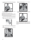
Hammering Only
Spline Drive System (Cat. No. 5319-21 & 5321-21)
When a chisel (or other “hammering-only” accessory) is mounted into the
5319-21 or 5321-21 Rotary Hammer, the rotational drive mechanism does
not engage with the chisel. The 5321-21 can use chisels in the “hammer-
ing-with-rotation” setting or the “hammering-only” setting.
NOTE: The 5321-21 Rotary Hammer must be set in the “hammering-
only” setting when setting self-drilling anchors. See “Setting Self-Drilling
Anchors" for complete instructions.
Selecting Speed
These rotary hammers have a speed control dial. The speed control dial
allows the user to adjust the rotating speed (RPM) and the impact rate
(BPM) of the tool.
To change the speed, set the speed control dial to the desired setting.
Lower speeds provide more control when starting holes and reduce ‘spalling’
on breakthrough. Spalling occurs when pieces of material chip off around the
drilled hole on breakthrough. When chiseling in soft or brittle materials, use
lower speeds to reduce damage to surrounding areas of the material.
Higher speeds provide for faster penetration when drilling and chiseling in
demolition work.
WARNING
2
1
Fig. 5
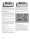
Cat. No.
5315-21
5315-22
only
1
Fig. 6
3
2
Cat. No.
5315-21
5315-22
5321-21
5321-22
Cat. No.
5315-21
5315-22
5321-21
5321-22