


6 7
Grounded tools require a three wire exten-
sion cord. Double insulated tools can use
either a two or three wire extension cord.
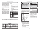
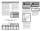
As the distance from the supply outlet
increases, you must use a heavier gauge
extension cord. Using extension cords with
inadequately sized wire causes a serious
drop in voltage, resulting in loss of power
and possible tool damage. Refer to the table
shown to determine the required minimum
wire size.
The smaller the gauge number of the wire,
the greater the capacity of the cord. For ex-
ample, a 14 gauge cord can carry a higher
current than a 16 gauge cord. When using
more than one extension cord to make up
the total length, be sure each cord contains
at least the minimum wire size required. If
you are using one extension cord for more
than one tool, add the nameplate amperes
and use the sum to determine the required
minimum wire size.
Guidelines for Using Extension Cords
• If you are using an extension cord out-
doors, be sure it is marked with the suffi x
“W-A” (“W” in Canada) to indicate that it
is acceptable for outdoor use.
• Be sure your extension cord is prop-
erly wired and in good electrical
condition. Always replace a damaged
extension cord or have it repaired by a
qualifi ed person before using it.
• Protect your extension cords from sharp
objects, excessive heat and
damp or wet areas.
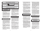
READ AND SAVE ALL INSTRUCTIONS FOR FUTURE USE.
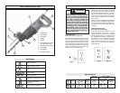
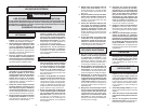
Recommended Minimum Wire Gauge
for Extension Cords*
Extension Cord Length
* Based on limiting the line voltage drop to
fi ve volts at 150% of the rated amperes.
Nameplate
Amperes
0 - 2.0
2.1 - 3.4
3.5 - 5.0
5.1 - 7.0
7.1 - 12.0
12.1 - 16.0
16.1 - 20.0
25'
18
18
18
18
16
14
12
75'
18
18
16
14
12
10
100'
18
16
14
12
10
150'
16
14
12
12
50'
18
18
18
16
14
12
10
EXTENSION CORDS
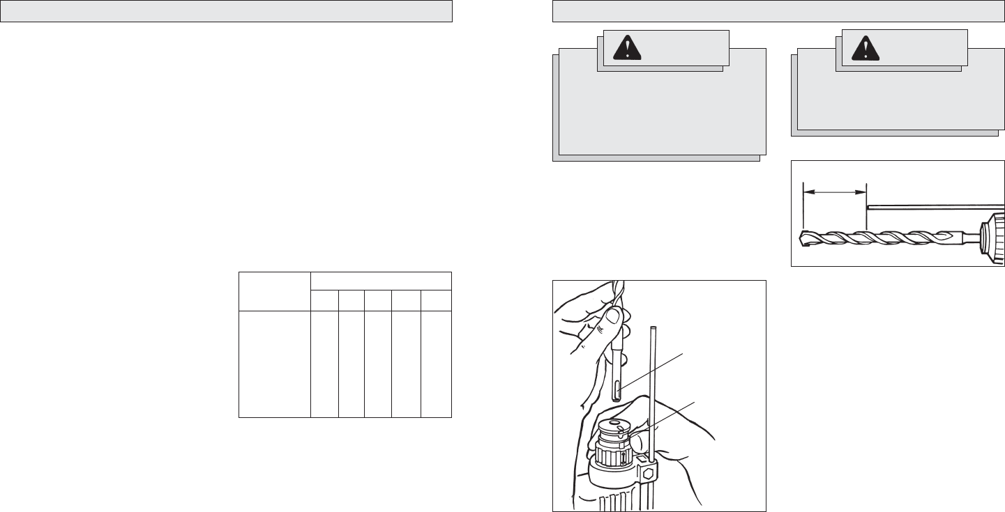
WARNING
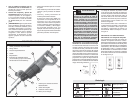
TOOL ASSEMBLY
To reduce the risk of injury, always
unplug tool before attaching or
removing accessories or making
adjustments. Use only specifi cally
recommended accessories. Others
may be hazardous.
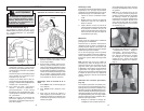
WARNING
To reduce the risk of injury, always
use a side handle when using
this tool. Always brace or hold
securely.
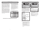
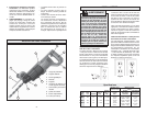
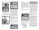
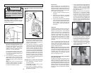
Installing Bits (Fig. 1)
This tool is designed with a universal drive
system that accepts SDS, SDS Plus and
Hilti TE-C bits. Always clean and lubricate
the shank of the bit before installing it into
your tool to help prevent heat build-up and
protect the bit shank from wear due to abra-
sive concrete dust.
1. Pull the chuck collar back toward the
tool.
2. Line up the recesses on the shank of the
bit with the marks on the chuck collar
as shown. Then, insert the bit into the
spindle as far as possible.
3. Release the chuck collar, locking the bit
into position. Rotate the bit slightly to be
sure it is locked securely.
4. To remove the bit, pull the chuck collar
back toward the tool, twist bit slightly and
remove.
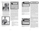
Adjusting the Depth Gauge (Fig. 2)
1. To adjust the position of the depth rod,
loosen the side handle.
2. Slide the depth gauge rod backward
or forward until it is set for the desired
depth.
NOTE: The drilling depth is the distance
between the tip of the bit and the tip of
the depth gauge rod.
3. Tighten the side handle securely.
Fig. 1
Recesses in
bit shank
Marks on
chuck collar
Fig. 2
Drilling
Depth