


4
5
grounding system and must never be attached to
an electrically “live” terminal.
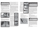
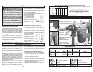
Your tool must be plugged into an appropriate out-
let, properly installed and grounded
in accordance with all codes and or-
dinances. The plug and outlet should
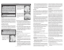
look like those in Figure A.
Double Insulated Tools:
Tools with Two Prong Plugs
Tools marked “Double Insulated” do not require
grounding. They have a special double insula-
tion system which satisfi es OSHA requirements
and complies with the applicable standards of
Underwriters Laborato-
ries, Inc., the Canadian
Standard Association
and the National Elec-
trical Code. Double In-
sulated tools may be
used in either of the 120
volt outlets shown in
Figures B and C.
Fig. B
Fig. C
Fig. A
GROUNDING
WARNING Improperly connecting the
grounding wire can result in the risk of elec-
tric shock. Check with a qualifi ed electrician
if you are in doubt as to whether the outlet is
properly grounded. Do not modify the plug
provided with the tool. Never remove the
grounding prong from the plug. Do not use
the tool if the cord or plug is damaged. If
damaged, have it repaired by a MILWAUKEE
service facility before use. If the plug will not
fi t the outlet, have a proper outlet installed by
a qualifi ed electrician.
Grounded Tools:
Tools with Three Prong Plugs
Tools marked “Grounding Required” have a three
wire cord and three prong grounding plug. The
plug must be connected to a properly grounded
outlet (See Figure A). If the tool should electrically
malfunction or break down, grounding provides a
low resistance path to carry electricity away from
the user, reducing the risk of electric shock.
The grounding prong in the plug is connected
through the green wire inside the cord to the
grounding system in the tool. The green wire in the
cord must be the only wire connected to the tool's
Grounded tools require a three wire extension
cord. Double insulated tools can use either a two
or three wire extension cord. As the distance from
the supply outlet increases, you must use a heavier
gauge extension cord. Using extension cords with
inadequately sized wire causes a serious drop in
voltage, resulting in loss of power and possible tool
damage. Refer to the table shown to determine the
required minimum wire size.
The smaller the gauge number of the wire, the
greater the capacity of the cord. For example, a 14
gauge cord can carry a higher current than a 16
gauge cord. When using more than one extension
cord to make up the total length, be sure each cord
contains at least the minimum wire size required. If
you are using one extension cord for more than one
tool, add the nameplate amperes and use the sum
to determine the required minimum wire size.
READ AND SAVE ALL
INSTRUCTIONS FOR
FUTURE USE.
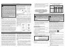
Recommended Minimum Wire Gauge
for Extension Cords*
Extension Cord Length
* Based on limiting the line voltage drop to
fi ve volts at 150% of the rated amperes.
Nameplate
Amperes
0 - 2.0
2.1 - 3.4
3.5 - 5.0
5.1 - 7.0
7.1 - 12.0
12.1 - 16.0
16.1 - 20.0
25'
18
18
18
18
16
14
12
75'
18
18
16
14
12
10
100'
18
16
14
12
10
150'
16
14
12
12
50'
18
18
18
16
14
12
10
EXTENSION CORDS
Guidelines for Using Extension Cords
• If you are using an extension cord outdoors,
be sure it is marked with the suffi x “W-A” (“W”
in Canada) to indicate that it is acceptable for
outdoor use.
• Be sure your extension cord is properly wired
and in good electrical condition. Always replace
a damaged extension cord or have it repaired by
a qualifi ed person before using it.
• Protect your extension cords from sharp objects,
excessive heat and damp or wet areas.
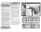
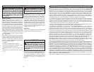
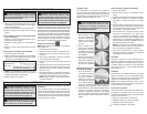
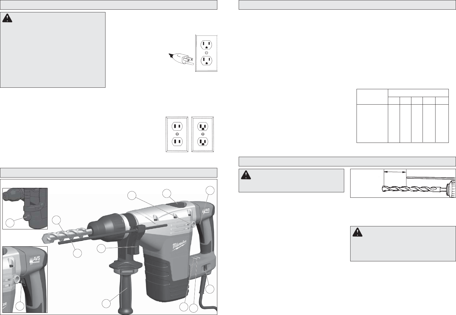
FUNCTIONAL DESCRIPTION
1. Bit holder
2 Rear side handle position
3. Mode selector
4. Trigger
5. Trigger lock-on (5446-21 only)
12
11
9
1
3
4
6
8
7
2
10
5
6. Hammer speed control
7. Power indicator
8. Service indicator
9. Side handle
10. Side handle ball
(5446-21 only)
11. Clamp
12. Depth gauge rod
ASSEMBLY
WARNING To reduce the risk of in-
jury, always unplug tool before changing or
removing accessories. Only use accessories
specifi cally recommended for this tool. Others
may be hazardous.
Adjusting the Side Handle Position
1. Loosen the side handle by unscrewing the side
handle grip (5426-21) or ball (5446-21) until the
side handle rotates freely.
2. Rotate the side handle to the desired position.
3. Tighten the side handle grip or ball securely.
Moving the Side Handle (Cat. No. 5426-21)
1. Remove the side handle by unscrewing the side
handle grip until it comes free.
2. Screw the side handle into the alternate loca-
tion.
3. Tighten the side handle grip securely.
Setting the Depth Gauge
1. Press in the clamp lever.
2. Slide the depth gauge rod backward or forward
until it is set for the desired depth.
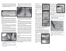
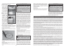
Fig. 1
Drilling Depth
Installing Drill Bits and Chisels
Be sure that the shank of the bit is clean. Dirt par-
ticles may cause the bit to line up improperly. Do not
use bits larger than the maximum recommended
capacity of the drill because gear damage or mo-
tor overloading may result. For best performance,
be sure that the bit is properly sharpened and the
shank is lightly greased before use.
NOTE: The drilling depth is the distance be-
tween the tip of the bit and the tip of the depth
gauge rod.
3. Release the clamp lever.
WARNING To reduce the risk of injury,
always use a side handle when using this tool.
Always brace or hold securely.