


page 8
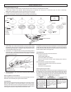
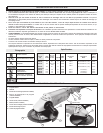
USING GRINDING AND CUT-OFF WHEELS
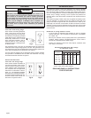
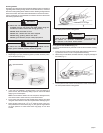
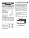
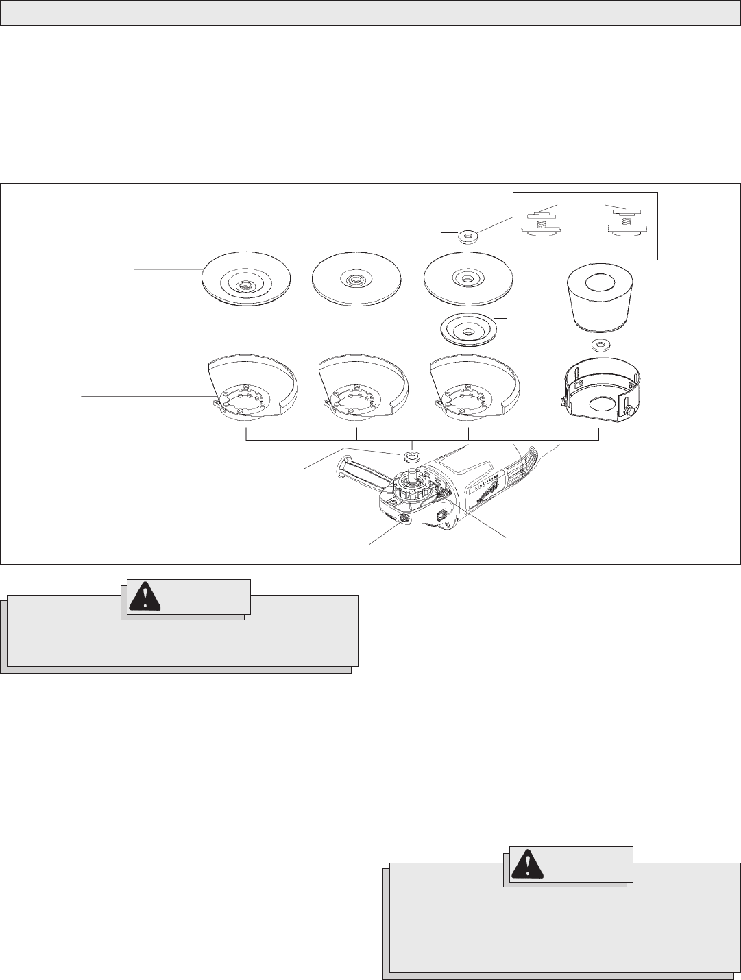
Fig. 8
Spindle
Grinding wheels
A. Type 28 with hub
B. Type 27 with hub
Type 29 with hub
C. Type 27 with flange
Type 29 with flange
D. Type 11
Disc nut
Nylon washer
Type 27
flange
Type 11
flange
BC
D
A
Spindle lock button
Guard
E. Type 28
F. Type 27
G. Type 27
H. Type 11
FG HE
1/4" thick
wheels
1/8" thick or
less wheels
Disc nut position
Troubleshooting
Deep scratches and circular marks can result from:
Uneven pressure
Using a partially glazed wheel - especially on aluminum applications
Dirt or loose metal on the workpiece
Failure to constantly move across surface
Bluish discoloration of metal surface indicates:
Excessive heat caused by circular motion in a small area
Excessive pressure
Use of worn out or glazed wheels
Inspecting Wheels
Always handle wheels carefully to avoid damage. Before installing any wheel,
always inspect it for cracks. If wheel is cracked, discard it to prevent others
from using it.
Care of Grinding & Cut-Off Wheels
Grinding and cut-off wheels should be protected from:
wetness and extreme humidity
any type of solvent
extreme changes in temperature
dropping and bumping
Grinding and cut-off wheels should be stored:
in an organized way so wheels can be removed without disturbing
or damaging other wheels
with their safety information
Grinding and cut-off wheels should NOT be:
dropped
rolled
bumped
If any wheel is dropped, rolled, bumped, subjected to extreme changes in
temperature, or has come into contact with solvents or wetness, discard wheel
immediately.
Installing Grinding Wheels (Fig. 8)
1. Unplug tool and place it upside down on a level surface as shown. Remove any accessories from spindle.
2. Thread nylon washer onto spindle. Attach guard and grinding wheel using Fig. 8 to determine type and order of assembly (See Fig. 2 and 3 for attaching
guard). NOTE: When installing Type 27 or Type 29 grinding wheels, position disc nut according to wheel thickness.
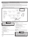
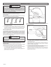
Position the guard in the location which offers best control and guard protection. For operating zones that provide maximum protection for the operator,
see Fig. 9. NOTE: When selecting Type 11 grinding cup wheels, the guards skirt should be adjusted so that no more than 1/8" of the wheel extends
beyond the guard.
3. To tighten, press the spindle lock button while turning wheel or disc nut clockwise using the spanner wrench provided.
4. To remove grinding wheel and guard, unplug tool and reverse procedure.
WARNING!
Only use wheels with Maximum Safe Operating Speed rated
at or above the RPM listed on the WARNING section of the
tool's nameplate. This speed is based on the strength of the
wheel, allowing for a reasonable measure of safety. It is not
meant to imply a best or most efficient operating speed. Do
not exceed the Maximum Safe Operating Speed.
WARNING!
To reduce the risk of injury, the operator should
be instructed in the use, care and protection of
grinding wheels.