


6 7
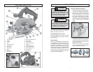
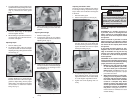
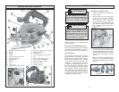
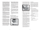
FUNCTIONAL DESCRIPTION
1. Lock-off button
2. Trigger
3. Handle
4. Shoe
5. Lower guard lever
6. Lower guard
7. Blade bolt
8. Blade fl ange
9. Blade
10. Sight line
11. Rip fence slot
19
21
20
12. Rip fence adjusting knob
13. Upper guard
14. Front handle
15. Depth setting gauge
16. Wrench
17. Spindle lock button
18. Depth adjusting lever
19. Bevel adjusting knob
20. Bevel pointer
21. Bevel scale
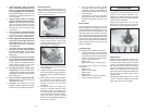
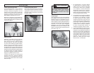
TOOL ASSEMBLY
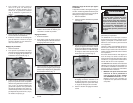
Bolt
Outer fl ange
Inner fl ange
Spindle
Fig. 2
WARNING
To reduce the risk of injury, always
remove battery pack before attaching
or removing accessories. Use only
specifi cally recommended accesso-
ries. Others may be hazardous.
Removing Battery Pack from Tool
Push in the release buttons and slide the
battery pack away from the tool.
Inserting Battery Pack into Tool
To insert the battery pack into the tool, push
in the release buttons and slide it into the
body of the tool.
Selecting Blade
Always use sharp blades. Dull blades tend
to overload the tool and increase the chance
of KICKBACK (see "Causes and Operator
Prevention of KICKBACK"). Only use thin
kerf blades with a maximum safe operating
speed greater than the no load RPM marked
on the tool's nameplate. Read the blade
manufacturer's instructions before use. Do
not use any type of abrasive cut-off wheel
or dry diamond cutting blades.
Fig. 1
Installing and Removing Blades
1. REMOVE BATTERY PACK BEFORE IN-
STALLING OR REMOVING BLADES.
2. Place the saw on a fl at surface with the
blade facing upwards. To remove the
bolt from the spindle, push in the spindle
lock button. While holding the spindle
lock button in, use the wrench provided
with the tool to turn the bolt clockwise
(Fig. 1). Remove the bolt and blade
fl ange.
3. Slide the lower guard lever up to raise
the lower guard. Remove the blade from
the spindle. Always clean the spindle,
upper guard and lower guard to remove
any dirt and sawdust.
NOTE: Do not remove inner blade
fl ange. Larger diameter of inner fl ange
(Fig. 2) should face the blade.
WARNING
Recharge only with the charger
specifi ed for the battery pack. For
specifi c charging instructions, read
the operator's manual supplied with
your charger and battery pack.
15
16
17
18
2
3
4
5
6
7
8
9
10
11
12
13
14
1